ASRock X79 Extreme11 Review: PCIe 3.0 x16/x16/x16/x16 and LSI 8-Way SAS/SATA
by Ian Cutress on September 3, 2012 10:15 AM EST- Posted in
- Motherboards
- ASRock
- X79
- LSI
- PLX
Testing the LSI SAS 2308 PCIe Controller
As part of this review, ASRock were kind enough to provide a set of eight ADATA XPG SX910 256GB drives in order to test the LSI SAS/SATA ports on the motherboard. These drives are rated for 500 MBps+ sequential read and write speeds, and are based on the LSI SF-2281 controller. Due to the routing of the LSI chip via PCIe 3.0 lanes, our bandwidth ceiling is lifted as we do not have to go via the chipset.
The LSI SAS controller supports SAS2 and SATA 6 Gbps drives. This is in comparison to the C60x server based chipsets for Sandy Bridge-E and Xeon processors based on the 2011 socket, which allow for up to eight SAS/SATA drives limited to SATA 3 Gbps and chipset throughput.
The LSI controller allows for RAID 0, 1 and 10 only, which is a little odd. I would have expected some users to require RAID 5 or 6. Running eight drives in RAID 0 is a unique real world scenario, due to the fail rate potentially wiping all the data, but it does allow us to study peak throughput. Thus the preferred scenario here will be RAID 10 across eight drives, thus taking advantage of striping across 4 of the drives but also having them mirrored.
The LSI platform is very easy to use. With the drives plugged in and powered (I had to rummage for suitable power connectors), the LSI software provided (MegaRAID) on the ASRock Driver DVD is loaded and run. After a login screen, we are presented with the following:
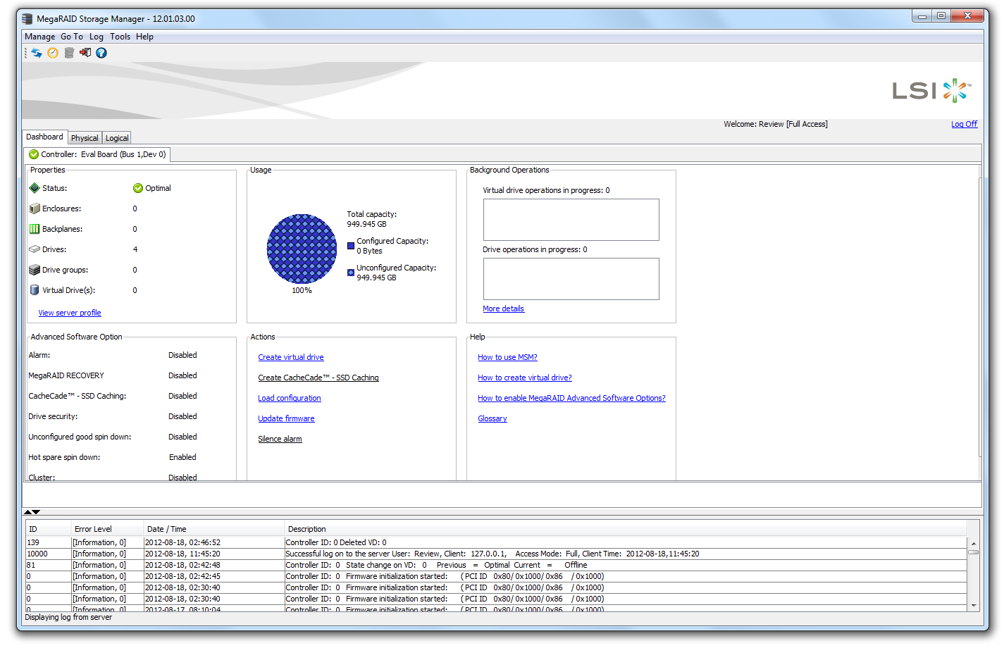
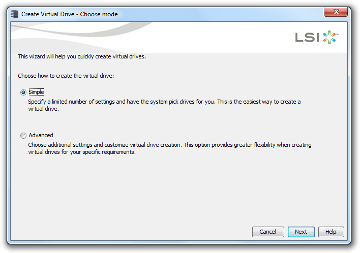
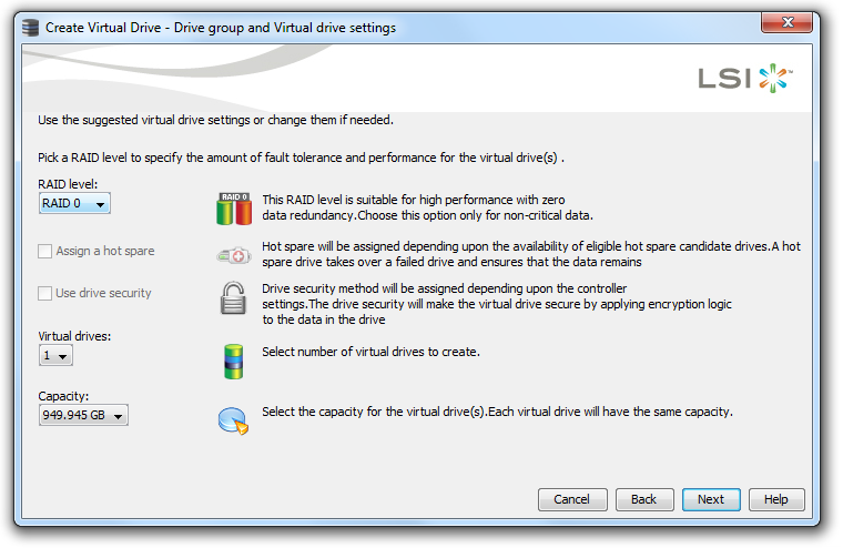
In order to create array, we select the ‘Create Virtual Drive’ option. We then get an option to select either an Easy mode for creating the virtual drive, or an advanced mode. Both are very limited in their options, especially as we can only choose one stripe size – 64KB.

The virtual drive then needs to be mounted in Windows, using the Disk Management tool.
The LSI chip by default is set to run in PCIe 3.0 mode in the BIOS. There is also an option to allow booting from the LSI chip, via Port 7. This unfortunately adds a large amount of time to the booting of the system, around 40-50 more seconds.
With this in mind, we tested several scenarios for bandwidth and 4K performance with the LSI chip. As the LSI has no access to additional cache like a PCIe card, we will see that the peak performance lies more in bulk sequential transfers, rather than small transfers.
For the tests, we used the standard ATTO benchmark and the following scenarios in RAID-0:
LSI Chip with 1, 2, 3, 4, 5, 6, 7, 8 drives (listed as SAS x) via MegaRAID
Chipset with 1, 2 drives on SATA 6 Gbps (listed as x+0)
Chipset with 1, 2, 3, 4 drives on SATA 3 Gbps (listed as (0+x)
Chipset with 1 drive on SATA 6 Gbps and 1, 2, 3, 4 drives on SATA 3 Gbps (listed as 1+x)
Chipset with 2 drives on SATA 6 Gbps and 1, 2, 3, 4 drives on SATA 3 Gbps (listed as 2+x)
All chipset scenarios were set using the RAID from BIOS rather than in the OS.
In terms of peak speeds using ATTO, we recorded the following results:
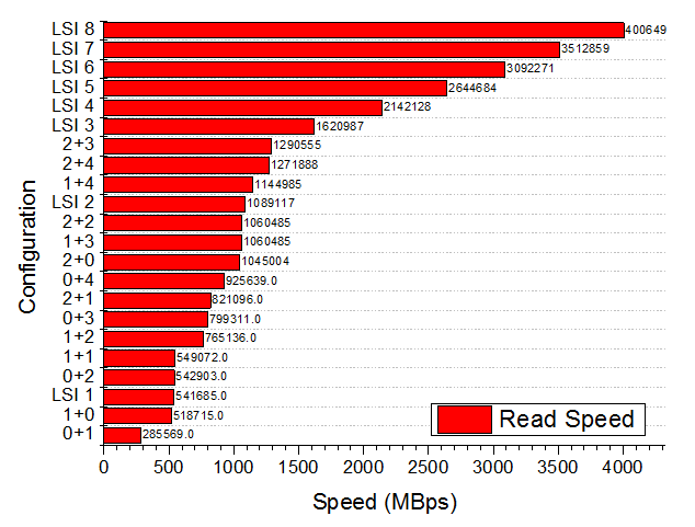
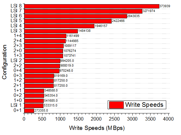
There are plenty of conclusions to draw from this – for peak throughput, the LSI ports are preferred. When using the chipset connections, going from 2+0 to 2+1 will bring a drop in performance. Also worthy of note is our top speed with eight drives in RAID-0 – we hit 4.0 GBps read and 3.72 GBps write. We can see more by looking at how the chipset deals with reads and writes differently to the LSI chip:
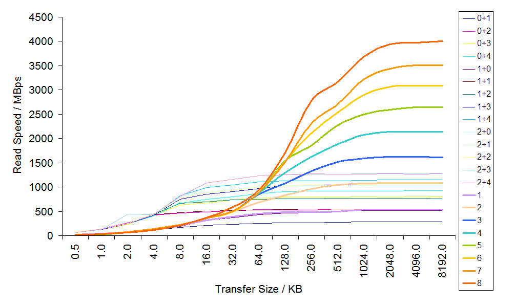
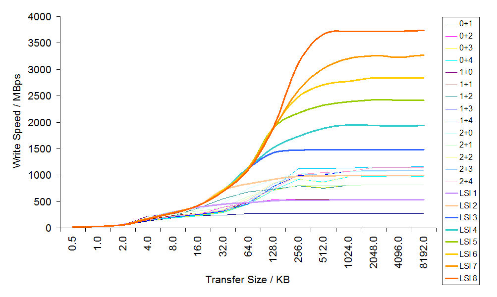
In terms of write speeds, all the drive configurations perform nearly the same until the advantage of more drives takes over, and the LSI configurations of 3+ pull ahead. However, in the read speeds, all the chipset configurations that feature at least one SATA 6 Gbps drive have distinctly better read speeds below 64 KB transfer size. This could be due to some chipset caching or clever manipulation of the data. Thus for standard OS drives, putting two drives on the chipset SATA 6 Gbps ports will be more beneficial than using the LSI chip.
In terms of scaling, the LSI chip has the following 3D surfaces for read and write:
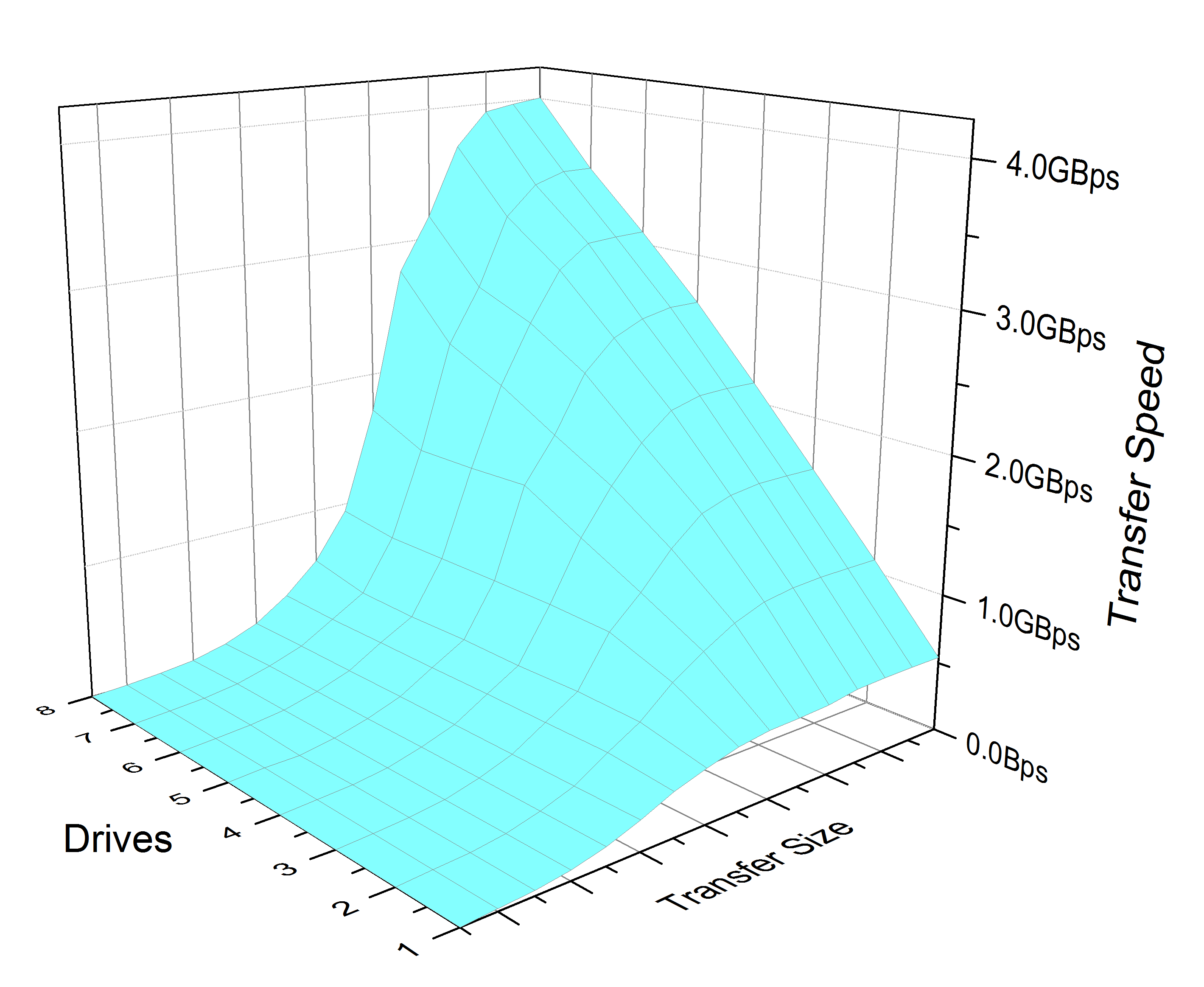
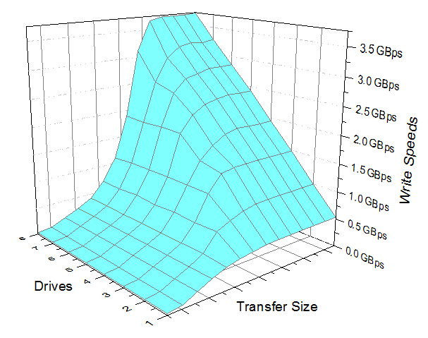
In both read and write, we only see any relevant scaling of drives beyond 128KB transfers. The large the transfer, the more the scaling becomes almost 1:1 as more drives are added.
Ultimately though, this may not be the best use case scenario for the product. As mentioned above, perhaps an eight drive RAID 10 array could be utilized with SAS drives, whereby the drive is more relevant to the speed than the port is (despite ASRock advertising stating peak throughputs).


62 Comments
View All Comments
StevoLincolnite - Monday, September 3, 2012 - link
Chipset fans.WHY!? They're noisy, probably fail quickly when filled up with dust...
I have the Asus Sabertooth x79 which has 2 small fans on it and the noise they generate drives me bonkers, thankfully the board has a 5 year warranty... Heck most of these chipset fans aren't even a standardized size so replacing them on your own is going to be tough/impossible.
Grebuloner - Monday, September 3, 2012 - link
I think you might want to check your board or your case cooling setup then. I can't hear the fans on my Sabertooth unless I stick my ear up to the grill on the I/O plate, and the chipset fan is inaudible over the 580 it sits next to.owan - Tuesday, September 4, 2012 - link
Its not rocket science, its right there in the review: 35+W underneath a very low-profile heatsink. Passive cooling just wasn't going to cut it. I swear, if people are going to complain about stuff on this motherboard, they could do a lot better than whinging about the fan.Master_shake_ - Tuesday, September 4, 2012 - link
i have an LSI 9260 add in card and that thing gets super hot, and the fan on this is really loud...just check out linus tech tips on youtube and you can hear it.
mike55 - Monday, September 3, 2012 - link
What are those little box-shaped components that are in the center of the CPU socket and appear in the dozens on every PCB I've ever seen?Ditiris - Monday, September 3, 2012 - link
They're capacitors for the CPU, more specifically decoupling capacitors.mike55 - Monday, September 3, 2012 - link
Ah, thanks! Good to finally know what the heck those things are.LamborghiniBooby43 - Monday, September 3, 2012 - link
As the X79 chipset does not have USB 3.0 as standard, ASRock have included Texas Instrument USB 3.0 controllers for a total of eight ports (4 on the back panel, 4 via two onboard headers) and a 2-port front USB panel included in the box. http://goo.gl/XbQv9JMC2000 - Monday, September 3, 2012 - link
If ASRock says this board is aimed at the workstation user, why in the world did they put those useless decorative metal shields on the heatsinks? Those things just scream out 'Gamer' to me.I would like to see someone build a dual-2011 socket board utilizing 4 of the PLX8747 chips.
Belard - Monday, September 3, 2012 - link
Yep... A Workstation board is just that... They don't need all the bling. Yes, this board has workstation features - but this looks nothing more than a board for an uber gamer who has money to spend.Of course, what game makes use of 4 gaming cards (yeah, the slots are only useful for rendering / compute type work).
Still, if you want to have EVERYTHING possible... this should be it.