Intel P965: Mid-Range Performance Sector Roundup
by Gary Key on October 20, 2006 9:00 PM EST- Posted in
- Motherboards
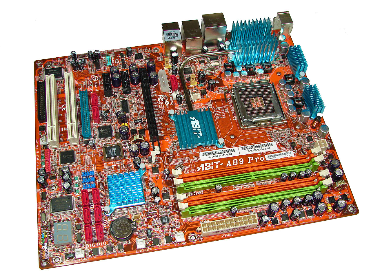
Abit AB9 Pro: Board Layout and Features
Abit designed a board that has one of the more interesting layouts we have seen in a long time. While the board was very easy to install in our mid-size ATX case we did have some issues with utilizing our Optical drive in the top bay due to the location of the JMicron powered IDE port that is located in between the number two PCI Express x1 slot and the number one PCI slot. There are six fan headers on the board that can be controlled by the µGuru Windows utility. The Abit board features an excellent five-phase voltage regulator power design with high quality capacitors located in each major component section of the board that yielded superb stability.
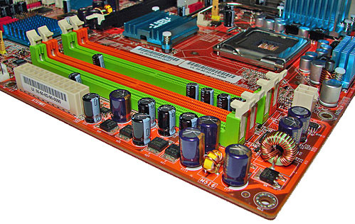
The DIMM module slots' color coordination is correct for dual channel setup based upon the premise of installing DIMMs in the same colored slots for dual-channel operation. The memory modules are easy to install with a full size video card placed in the first PCI Express x16 slot. The 24-pin ATX power connector is located along the edge of the board along with a series of capacitors for the memory modules. Abit places the four-pin 12v auxiliary power connector at the top of the first memory module but completely out of the way of aftermarket cooling solutions we utilized.
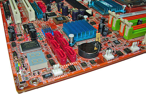
The six Intel ICH8R SATA ports are color coded red and are conveniently located to the left of the ICH8R Southbridge and battery. The SATA ports feature the newer clamp and latch design. We found the positioning of the SATA ports to be excellent when utilizing either the PCI-E x1 or PCI 2.3 slots. The ICH8R is passively cooled and remained cool to the touch throughout testing.
The first three of five auxiliary fan connectors are located at the bottom edge of the board. The clear CMOS jumper is color coded yellow and is located in between the battery and ICH8R chipset. The CP80P post port debug LED, chassis panel, µGuru chipset, and red 1394a connectors are located along the left edge of the board. The blue USB 2.0 connectors are located above the SATA ports.
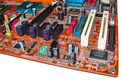
The board comes with (1) physical PCI Express x16 connector, (2) PCI Express x1 connectors, and (2) PCI 2.3 connectors. The layout of this design offers a very good balance of expansion slots for a mainstream board while providing excellent clearance space for graphics card utilization. However, the layout in this area is very unusual if not a bit chaotic. Our main issue is the location of the floppy drive connector at the bottom of the board along with the JMicron JMB363 IDE and SATA ports being sandwiched in between the PCI-E and PCI slots in the middle of the board.
The four-pin Molex power connector that will be required for future GPU products is located above the PCI-E x16 slot along with the Silicon Image 3132 SATA port. Abit informed us some of the unusual port locations were predicated upon ensuring proper power delivery, stability, and trace layouts based upon the capacitor locations. However, we still have to wonder if some of these layout choices were design gaffe that accidentally made it into production.
Returning to the CPU socket area, we find an ample amount of room for alternative cooling solutions. We utilized the stock heatsink/fan in our normal testing but also verified a couple of larger Socket-775 cooling solutions such as the Tuniq Tower 120 would fit in this area during our overclocking tests.
The Intel P965 MCH chipset is passively cooled with a low rise heatsink unit that did not interfere with any installed peripherals. This heatsink is part of the Abit Silent OTES technology that includes a heatpipe system and additional passive cooling for the VRM components. This system kept the MCH cool enough that additional chipset voltage was not a factor in our overclocking tests.
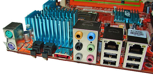
The rear panel contains the standard PS/2 mouse and keyboard ports, LAN ports, and 4 USB ports. The LAN (RJ-45) ports have two LED indicators representing Activity and Speed of the connection through the Realtek RTL8168 Gigabit PCI-E chipset. The audio panel consists of 6 ports that can be configured for 2, 4, 6, and 8-channel audio connections for the Realtek ALC 882D HD codec. The panel also consists of two S/PDIF (optical in/optical out) ports, and an external SATA 3Gb/s port via the Silicon Image 3132 chipset. All in all, Abit included an excellent combination of ports although another two USB ports would have been handy for additional peripherals.
 |
| Click to enlarge |
Abit designed a board that has one of the more interesting layouts we have seen in a long time. While the board was very easy to install in our mid-size ATX case we did have some issues with utilizing our Optical drive in the top bay due to the location of the JMicron powered IDE port that is located in between the number two PCI Express x1 slot and the number one PCI slot. There are six fan headers on the board that can be controlled by the µGuru Windows utility. The Abit board features an excellent five-phase voltage regulator power design with high quality capacitors located in each major component section of the board that yielded superb stability.
The DIMM module slots' color coordination is correct for dual channel setup based upon the premise of installing DIMMs in the same colored slots for dual-channel operation. The memory modules are easy to install with a full size video card placed in the first PCI Express x16 slot. The 24-pin ATX power connector is located along the edge of the board along with a series of capacitors for the memory modules. Abit places the four-pin 12v auxiliary power connector at the top of the first memory module but completely out of the way of aftermarket cooling solutions we utilized.
The six Intel ICH8R SATA ports are color coded red and are conveniently located to the left of the ICH8R Southbridge and battery. The SATA ports feature the newer clamp and latch design. We found the positioning of the SATA ports to be excellent when utilizing either the PCI-E x1 or PCI 2.3 slots. The ICH8R is passively cooled and remained cool to the touch throughout testing.
The first three of five auxiliary fan connectors are located at the bottom edge of the board. The clear CMOS jumper is color coded yellow and is located in between the battery and ICH8R chipset. The CP80P post port debug LED, chassis panel, µGuru chipset, and red 1394a connectors are located along the left edge of the board. The blue USB 2.0 connectors are located above the SATA ports.
The board comes with (1) physical PCI Express x16 connector, (2) PCI Express x1 connectors, and (2) PCI 2.3 connectors. The layout of this design offers a very good balance of expansion slots for a mainstream board while providing excellent clearance space for graphics card utilization. However, the layout in this area is very unusual if not a bit chaotic. Our main issue is the location of the floppy drive connector at the bottom of the board along with the JMicron JMB363 IDE and SATA ports being sandwiched in between the PCI-E and PCI slots in the middle of the board.
The four-pin Molex power connector that will be required for future GPU products is located above the PCI-E x16 slot along with the Silicon Image 3132 SATA port. Abit informed us some of the unusual port locations were predicated upon ensuring proper power delivery, stability, and trace layouts based upon the capacitor locations. However, we still have to wonder if some of these layout choices were design gaffe that accidentally made it into production.
 |
| Click to enlarge |
Returning to the CPU socket area, we find an ample amount of room for alternative cooling solutions. We utilized the stock heatsink/fan in our normal testing but also verified a couple of larger Socket-775 cooling solutions such as the Tuniq Tower 120 would fit in this area during our overclocking tests.
The Intel P965 MCH chipset is passively cooled with a low rise heatsink unit that did not interfere with any installed peripherals. This heatsink is part of the Abit Silent OTES technology that includes a heatpipe system and additional passive cooling for the VRM components. This system kept the MCH cool enough that additional chipset voltage was not a factor in our overclocking tests.
The rear panel contains the standard PS/2 mouse and keyboard ports, LAN ports, and 4 USB ports. The LAN (RJ-45) ports have two LED indicators representing Activity and Speed of the connection through the Realtek RTL8168 Gigabit PCI-E chipset. The audio panel consists of 6 ports that can be configured for 2, 4, 6, and 8-channel audio connections for the Realtek ALC 882D HD codec. The panel also consists of two S/PDIF (optical in/optical out) ports, and an external SATA 3Gb/s port via the Silicon Image 3132 chipset. All in all, Abit included an excellent combination of ports although another two USB ports would have been handy for additional peripherals.


62 Comments
View All Comments
smn198 - Monday, October 23, 2006 - link
Would you be able to re-run using 4 drives for all of the tests please?
jonp - Sunday, October 22, 2006 - link
-- “…budget sector and includes boards from ECS, Foxconn, Intel, and Gigabyte.” – will the MSI P965 Neo-F be in this set?-- the Abit AB9 Pro feature set does not show the eSata port on the SI 3132 (two SATA). it does show a serial port on the i/o panel but not one in the picture.
-- The Biostar feature set shows 4 USB on the i/o panel when there are six in the picture.
JarredWalton - Sunday, October 22, 2006 - link
Fixed - thanks.powchi - Saturday, October 21, 2006 - link
Can I use a 20-pin power supply on these boards since all are using 24-pin connectors? Or will I be needing 20pin to 24pin adaptor?The PSU is an Enermax NoiseTaker EG475P-VE SFMA 470W ATX 12V v1.3.
Aikouka - Sunday, October 22, 2006 - link
Some motherboard manufacturers will no longer support your motherboard if they find out you've been running it with a 20-pin ATX plug or a 20->24-pin adapter. Just be safe and get a newer PSU :). I know DFI will no longer support the motherboard if it specifically asks for a 24-pin.JarredWalton - Saturday, October 21, 2006 - link
Technically, yes you can use 20-pin PSUs. Will they work, and will the system be stable? That varies. I haven't had any issues on the systems where I've done it, but if you do high overclocking it will likely become a serious issue.powchi - Saturday, October 21, 2006 - link
Jarred,So there's no need to use a 20pin to 24pin adaptor? What are the differences when using and not using an adaptor? Thanks.
lopri - Sunday, October 22, 2006 - link
No. As a matter of fact, the adapter should be avoided. Just plug the 20-pin connector to 24-pin receptacle with 4-pin left empty. Like Jarred said, it should work in theory and it does in practice. However, the quality of PSU and how intense is one's OC can affect the (long-term) stability.JarredWalton - Sunday, October 22, 2006 - link
I suppose the adapter *could* help, as it ensures power is available on all the 24-pins, but you're still taking the power from the same source so depending on how that works out it can actually make things worse. I would typically say that if you have a 400W or better PSU you should be fine with little to moderate OC'ing even with 20-pins. (I have an OCZ ModStream 450W that certainly works fine in a 939 board with a decent 2.0 to 2.6 GHz overclock.)lopri - Sunday, October 22, 2006 - link
Yes! Not to brag about myself or anything, but I went through countless Socket 939 Opterons on DFI NF4 SLI-D with original Antec TruePower EPS12V (20-pins, not the TP2 with 24-pins) including an Opteron 165 @3.0GHz (9x333). TCCD up to 325MHz/2.5-4-3-8! The setup was absolutely stable.