An AMD Threadripper X399 Motherboard Overview: A Quick Look at Seven Products
by Ian Cutress & Joe Shields on September 15, 2017 9:00 AM ESTThe MSI X399 SLI Plus
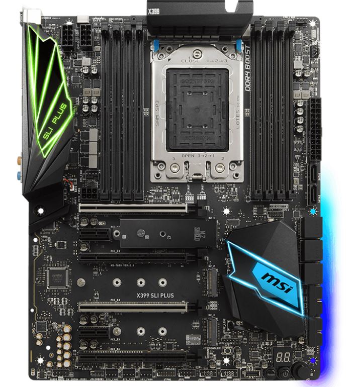
As with other X399 boards, the MSI X399 SLI Plus uses eight total memory slots, although these are not reinforced. This configuration allows for up to 128GB of RAM in a quad channel setup. MSI uses their DDR4 Boost technology on the SLI Plus and lists memory speed support up to DDR4-3600+.
Power delivery is handled by a fully digital 13 phase VRM which looks quite similar to the Gaming Pro Carbon AC. Per the Military Class VI specs, it uses Titanium chokes and 'dark' capacitors. We cannot confirm by the pictures, however, it is likely using the same DrMOS ICs found on the Pro Carbon. Power is fed to the VRMs by two 12V CPU leads (one is optional) located in the upper left-hand corner of the board. The SLI Plus has a full two character debug LED as well as a simplified four LED debug system with LED’s for Boot, VGA, DRAM, and CPU.
The SLI Plus has a total of six PCIe slots: two PCIe 2.0 x1 slots and four full-length PCIe 3.0 slots. The two main GPU slots, capable of running x16/x16 if they are the only ones populated, are reinforced with MSI’s Steel Armor to support heavy video cards and prevent potential damage to the slot. The motherboard supports 4-Way NVIDIA SLI and 4-Way AMD Crossfire technologies.


For storage, the SLI Plus has a total of eight SATA ports fed from the chipset, and has the same physical location and orientation of the Pro Carbon; six horizontal and two vertical. There are a total of three PCIe 3.0 x4 M.2 slots which get their lanes from the CPU. Two of the M.2 slots support up to 80mm drives, while the middle slot can handle up to 110mm modules. Only the top M.2 slot has a heatsink for cooling down the installed M.2 module. U.2 support does not make it to the SLI Plus.
The audio side of the house is managed by a Realtek ACL1220 codec working in conjunction with MSI’s Audio Boost 4 suite. While the Nahimic software package normally found on the gaming products does not make its way here, the SLI Plus uses separate audio layers for left and right channels, de-pop protection, Chemi-Con audio capacitors, EMI shielding and board separation, and a dedicated headphone amplifier which auto-detects impedance (use up to 600Ω).
As far as the overall aesthetic, MSI uses a black PCB and color scheme and lets the integrated RGB LEDs fit whatever theme a builder has in mind. LEDs make it on the back panel IO shroud, chipset heatsink, and a strip found on the back of the board under the SATA ports. Additional RGB LED strips can be added via the two onboard RGB headers. One is for a rainbow strip, while the other for general RGB; both are controlled by MSI’s Mystic Light software.
Pricing was not listed, but we do expect the SLI Plus to come in under the Gaming Pro Carbon. We should see these available for purchase soon.
| MSI X399 SLI PLUS | |
| Warranty Period | 3 Years |
| Product Page | Link |
| Price | N/A |
| Size | ATX |
| CPU Interface | TR4 |
| Chipset | AMD X399 |
| Memory Slots (DDR4) | Eight DDR4 Supporting 128GB Quad Channel Up to 3600 MHz (OC) Supports ECC UDIMM (in non-ECC mode) |
| Network Connectivity | 1 x Intel Gigabit LAN controller |
| Onboard Audio | Realtek ALC1220 |
| PCIe Slots for Graphics (from CPU) | 4 x PCIe 3.0 x16 |
| PCIe Slots for Other (from Chipset) | 2 x PCIe 2.0 x1 |
| Onboard SATA | 8 x Supporting RAID 0/1/10 |
| Onboard SATA Express | None |
| Onboard M.2 | 3 x PCIe 3.0 x4 - NVMe or SATA |
| Onboard U.2 | None |
| USB 3.1 | 1 x Type-C (ASMedia) 1 x Type-A (ASMedia) 1 x Internal Header |
| USB 3.0 | 4 x USB 3.0 |
| USB 2.0 | 2 x Back Panel 2 x Headers |
| Power Connectors | 1 x 24-pin ATX 2 x 8-pin CPU |
| Fan Headers | 1 x CPU (4-pin) 1 x Water Pump (4-pin) 4 x System Fan (4-pin) |
| IO Panel | 1 x Clear CMOS button 1 x BIOS FLASHBACK+ button 1 x PS/2 keyboard/mouse combo port 2 x USB 2.0 Type-A ports 8 x USB 3.0 Type-A ports 1 x LAN (RJ-45) 1 x USB 3.1 Type-A port 1 x USB 3.1 Type-C port 5 x Audio Jacks 1 x Optical S/PDIF OUT connector |


99 Comments
View All Comments
vgray35@hotmail.com - Saturday, September 16, 2017 - link
A few % better - you are looking at it wrong. Platinum PSU units with peak 94% efficiency means 6% heat dissipated. Now at 99% efficiency that is 1% dissipated as heat. That means a 5/6th reduction in heat or 83% less heat which is not just a few percent better. Further the new topology yields a >70% cost reduction which is also not insignificant. Gas turbines are also too noisy by the way, which is the main reason these are not considered (expensive when they go wrong too), and thus not a good comparison versus improvements being discussed here. Are you saying the linked article on PWM-resonance and resonance scaling topology is not worthwhile, or the problems with Buck converter inductors is not a severely limited and highly noisy power solution? Perhaps Power Electronics engineering is not your field of interest at all!Manch - Monday, September 18, 2017 - link
ICE is not 60% less efficient than a gas turbine. A gas turbine doesn't scale downward well. One of similar power would actually less efficient as an equivalent rated ICE. Gas turbines are impractical for vehicles.One benefit of a turbine would be no tailgating. The intake would suck in and crap out small critters all over your windshield.
vgray35@hotmail.com - Friday, September 15, 2017 - link
Yes I appreciate that - we draw power (Watts) at the rate of Joules of energy per second, Notice I said "we draw power", but that is also directly reflected proportionally as current in Amps (or a rate of Coulombs per sec), There was not a direct inference that power is measured in Amps, but only (a) "We are drawing a measure of power", and (b) this is approaching proportionally a resultant 150A. Yes I probably could have said better, but in wise did I say power is measured in AMPS.vgray35@hotmail.com - Friday, September 15, 2017 - link
I do not believe a defacto motto of the industry is "we are wasting 5% in heat, so let us not bother with wasting only 1%). Clearly you did not read the link to the Power Electronics article (I surmise), as then you would have realized the solution offers a huge reduction in cost as well as heat. The cost factor is something everybody is interesting in, even the industry at large, in my humble opinion.ddriver - Friday, September 15, 2017 - link
Huge? Like what? 6-7% better? Maybe 8-9%?What I meant is the solution you linked to is like 99% efficient, a good buck converter is what? Like 90-92%?
That's nowhere near the difference between an internal combustion engine and a gas turbine, the latter being more than twice more efficient. And still no adoption, even thou the solution is not really all that complex, and decades old. They still only use gas turbines in the most demanding applications, which is pretty much the same as with the converters from that article, which that dude developed for NASA's most demanding applications. I am pretty sure computers in NASA run on buck converters too, and they will use his designs only for the stuff they launch into space.
You probably don't realize how immense of an impact it would have if all cars on the planet become more than twice as efficient, burning more than twice as little fuel, outputting less than half the harmful emissions, traveling twice as far on a single fill. It would completely dwarf the benefits of boosting computer power converters from 90 to 99% :)
I am not saying it is not cool, I am just saying there have been a lot more beneficial a lot more high priority solutions that haven't been adopted yet for a lot longer, so you should not be surprised that the entire industry hasn't switched to a new power converter design overnight. They will do as they will always do, they will milk the cow until it dies, and then make it into jerky, and only then will then go for the new and better thing.
vgray35@hotmail.com - Saturday, September 16, 2017 - link
As noted earlier, 92% which is 8% heat versus 99% which is 1% heat means a 7/8th reduction in heat or 87% reduction. Thinking this is only a 7% improvement differential is incorrect - it is in this example an 87% improvement. That is not small potatoes. When this is coupled with a corresponding large cost reduction, then it becomes apparent the chip manufacturers would rather make more money using the older technology. Maybe the PSU engineers are just plain lazy or are not following the advances in their field as they are snowed under with work.Let's keep the discussion focused on power supplies.vgray35@hotmail.com - Saturday, September 16, 2017 - link
The 600W @ 12V fed to the motherboard with ~8% losses is ~50W heat in the VRMs (driving 180W CPU, 320W GPU, leaving 100W for other parts), The ATX power supply is 90% efficient or less with 60W heat also in the same case. The GPU power supply also is another 25W waste power supply heat, for a total of 135W of waste heat (as opposed to the useful heat generated within the various components themselves, which is heat generated from useful work being done). It is tough to manage this 660W in the case, but over 135W of it (>21% low ball estimate) is waste heat from just power supplies alone (ATX PSU, VRMs, GPU supply), of which over 80% or 110W could be eliminated by abandoning the Buck converter topology. This of course is a simplistic view, as there are other components too that are ignored here, for brevity's sake. I suspect >25% of heat comes from power supplies alone which can be dramatically curtailed. It's a 3 ringed circus: ATX PSU steals 10% for itself, motherboard steals another 8% for itself and GPU steals a further 8% for itself. We have no control over the power drawn from the mega chips themselves, but we do have control over the power supplies that drive them, and manufacturers could be doing a lot better here. And this is by no means a monster power hungry system with only one high-end graphics card. A >85% reduction in power supply waste heat can be realized if the Buck converter is abandoned, and that applies to resonant LLC power supplies also. The motherboard manufacturers and ATX PSU manufacturers need to take this aspect much more seriously.http://www.powerelectronics.com/power-management/s...
AMD's Thread Ripper X399 and Intel's X299 platforms should have been their first attempt at abandoning the Buck, half-bridge, and resonant LLC topologies. They failed us in that regard. We need this fiasco to come to an end by using hybrid PWM-resonant switching and resonance scaling, which eliminates the ferrite cored inductors altogether, and replaces them with just copper traces on the PCB. This is not rocket science.
Oxford Guy - Saturday, September 16, 2017 - link
Motherboard makers seem pretty much incompetent. They can't even be bothered to issue BIOS updates to fix serious bugs.ddriver - Sunday, September 17, 2017 - link
Yeah, but then again, an overclocked TR is like 200W, even an entry level car is like 200 KILOWATTS. So percentages are not really that much indicative.The facts remain. A TR mobo with a better power regulator circuit will save like 10 watts of power, a car with a gas turbine engine will save like 100 KW of power.
That's 10 000 times larger saving measured on absolute scales. What's more important in your opinion? Saving a watt, or saving 10 000 watts? Naturally, I'd rather have both. The goal here is to illustrate how low of a priority it is to improve mobo power delivery compared to some other, longer standing improvement opportunities that have been ignored.
Icehawk - Sunday, September 17, 2017 - link
They tried turbine cars, they are terrible due to the way they deliver power. Several successful drag cars have used them as in that application the power delivery works well. Same reason we aren't going to be driving rocket cars.