Cooler Master Silent Pro PSUs
by Christoph Katzer on September 8, 2008 3:00 AM EST- Posted in
- Cases/Cooling/PSUs
Testing with the Chroma ATE Programmable Load
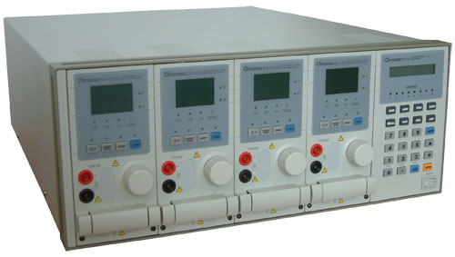
Our test equipment consists of two Chroma programmable DC Loads that enable us to test power supplies with an output of up to 1500W. The biggest advantage of the Chroma DC Loads is simply the high precision it provides. It can measure differences as small as 0.001V and 0.0001A, which will provide us with best-in-class results.
When programming the Chroma with specific amounts of load calculated according to the ATX norm, we are able to load power supplies to an exact percentage. We can now show results at every specific percentage needed. To get the best overview of a power supply, we load each unit with 10%, 20%, 50%, 80%, 100%, and 110% of the specified output. This is easy to calculate for a 1000W power supply: the 10% load is 100W and 110% load is 1100W. Remember that this is the amount of power the PSU delivers; due to inefficiencies, a power supply will actually draw more power from the wall.
Note: If you would like to know more about our testing methodology, equipment, and environment, please read our PSU testing overview.
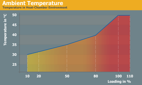
We have added an additional 10% on the highest load to see how the units perform with overload. This test will be performed in all future reviews. The overload test is performed at room temperature as well as under more stressful conditions; to ensure we are not too cruel to the power supplies, we will keep the ambient temperature at 50°C in the stress test. Experience shows that many units can stand the overload at room temperature but will experience problems with higher temperature and overload together. Only the best-built units will survive this.
The Testing Environment
There is one flaw in testing power supplies with programmable loads while trying to measure the sound pressure levels at the same time. Because the programmable loads get very loud, there is no chance of hearing the power supply on the test stand. In order to make accurate measurements of the noise levels we needed a way to separate the test unit and the programmable loads. Our solution was to build a very thick box around the unit.
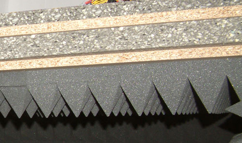
We concluded that a five-layer box with a total thickness of 6" (15cm) containing two layers of wood and three layers of special foam would suffice. It is designed as a box within a box. The inner box does not touch any part of the outer box, making it difficult for acoustic noise to pass through in the form of vibration. Each box is isolated on both sides with a layer of heavy foam that is normally used to insulate engines. On the inside we have an additional layer of 4" (10cm) thick pyramidal foam on every side of the box to eliminate the acoustic waves coming from the test object as well as we can.
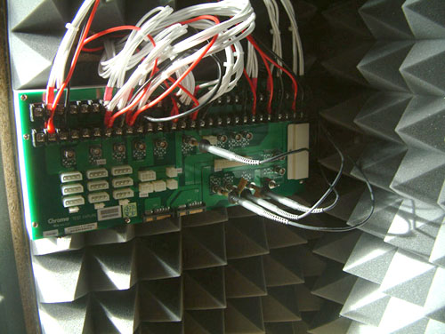
To ensure a completely closed system we installed the printed circuit board that the connectors of the power supply are attached to inside the anechoic room/box. In other box designs, you would need to put all the cables through the wall. Unfortunately, that would result in the inside of the box not being fully isolated anymore. Our design keeps everything that needs to be connected inside of the box and maintains isolation.


15 Comments
View All Comments
ryboto - Wednesday, September 17, 2008 - link
You're quite incorrect. The method for heat transfer from the heatsinks to the air is the same for both copper and aluminum. If you took a heat transfer course you'd know that the thermal conductivities and convective heat transfer coefficients are what is used in the heat transfer equations. No where is it dependent on the heat capacity. So, you haveQ=K A (Tb-Th) where Tb=base temp, Th= heatsink temp, then heat transfer to the air is
Qa=h A (Th-Ta) where Ta is the bulk air temp. These are highyl approximated, as there are multiple layers. Now, look at the equations...if K for Cu is greater than for Al, heat transfer is faster. What this amounts to is a greater Th, but look at the second equation, if Th is greater, the temperature gradient(or driving force for heat transfer) is greater than it would be for aluminum. Copper is a better material for this application. It's just expensive, and it oxidizes, which is why we have nickel plated copper heatpipes.
Megaknight - Tuesday, September 9, 2008 - link
Great explanation mate.Penti - Monday, September 8, 2008 - link
It's an old tale but it's just that a tale.Weight has probably a lot to do with it on modern coolers, I have a Tuniq Tower 120, think of this cooler in pure copper, it would snap the motherboard with it's weight probably. We haven't moved to coolers weighing 2-3 kg yet. But as always price is the main factor.
Aquila76 - Monday, September 8, 2008 - link
'Transfer' and 'dissipate' are different things. The copper plates transfer heat away from the components better; the aluminum fins dissipate (exchanges may have been a better word choice there) the heat into the air. This is not unlike those heatpipe tower-style CPU coolers.Christoph Katzer - Monday, September 8, 2008 - link
Thanks mate.