The Single 12V Rail SilverStone Olympia OP650
by Christoph Katzer on July 13, 2007 12:00 PM EST- Posted in
- Cases/Cooling/PSUs
Testing
We have already described our test setup and methodology here. Due to increasing heat the lower voltage rails will most likely decrease in output. This results from the tremendous ambient temperature in which we are testing power supplies and does not necessarily reflect what you will have in your PC at home. This is essentially a worst case test with respect to heat, and if the PSU performs well in our environment, you can be assured it will perform well in your PC. We are testing with 115VAC and 230VAC to cover all markets. To make the voltage drop more visible we will include graphs instead of tables. Above and below the dashed lines are out of spec values. Everything within these lines is within the specs and therefore acceptable.
To properly load the power supply we are using a Chroma DC Load. In this way we are able to put a specific amount of load on each of the connected rails. We are testing in ten steps beginning with 10% load and ending with 100% of each power supply's maximum output. The total procedure is taking us 5 hours for each of the two input voltages.
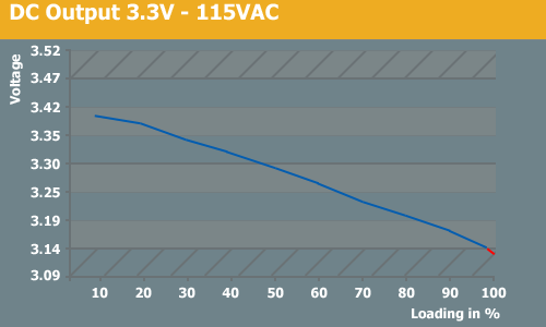
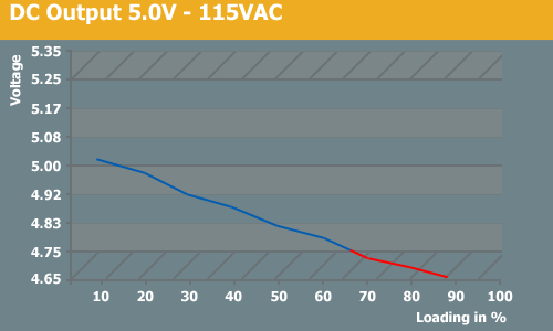
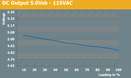
115VAC 3.3V, 5V, and 5Vsb Tests
The lower voltage rails have dropped hard during the test and they went under specification at about 80-90% of load. The 5v rail dropped under spec at around 65% load. With 230VAC things looked a little better. This could have been partly because we tested 230V first and the power supply might have been sweating it.
We have already described our test setup and methodology here. Due to increasing heat the lower voltage rails will most likely decrease in output. This results from the tremendous ambient temperature in which we are testing power supplies and does not necessarily reflect what you will have in your PC at home. This is essentially a worst case test with respect to heat, and if the PSU performs well in our environment, you can be assured it will perform well in your PC. We are testing with 115VAC and 230VAC to cover all markets. To make the voltage drop more visible we will include graphs instead of tables. Above and below the dashed lines are out of spec values. Everything within these lines is within the specs and therefore acceptable.
To properly load the power supply we are using a Chroma DC Load. In this way we are able to put a specific amount of load on each of the connected rails. We are testing in ten steps beginning with 10% load and ending with 100% of each power supply's maximum output. The total procedure is taking us 5 hours for each of the two input voltages.
115VAC 3.3V, 5V, and 5Vsb Tests
The lower voltage rails have dropped hard during the test and they went under specification at about 80-90% of load. The 5v rail dropped under spec at around 65% load. With 230VAC things looked a little better. This could have been partly because we tested 230V first and the power supply might have been sweating it.


46 Comments
View All Comments
Araemo - Friday, July 13, 2007 - link
That makes sense, and makes me think my guess about the 20A limit is possibly a contributing factor - It would be a safety issue if someone hung 40A worth of fans, lights, motorized case windows, whatever you want.. off of one pair of wires (IE, one molex connector feeding into the mass of extenders and passthrough connectors that most fans and lights I've seen use.).You'd likely overheat the wires carrying all that power, if not the connectors as well, which could cause fire or electrocution hazards.
While a GPU may draw significantly more than 20A, they are also using 3 pairs now, so the actual power draw will be closer to 20A per pair.
DerekWilson - Friday, July 13, 2007 - link
The PCIe V2.0 PSUs I've seen suggest only using connectors from the same 12V rail for PCIe graphics cards -- because if you don't, you'll be connecting the common from two different 12V rails together.This can cause issues.
If a graphics card has one 4pin and 1 8pin connector, like the HD 2900 XT, the GPU can potentially draw up to 225W from a single 12V rail through 2x PCIe graphics power connectors (3 pairs). That's about 19 amps through one rail for one PSU, but not over each pair.
SilthDraeth - Friday, July 13, 2007 - link
They explained it.The Intel ATX standard calls for no more than 20 Amps per 12V rail. So in order to avoid maxing out a single 12V rail at 20 Amps, PSUs have multiple rails support up to 20 Amps each.
If you use a single rail that can max out at 54 Amps as stated here, then you do not need the additional rails, but you are going against the ATX standard.
Duraz0rz - Friday, July 13, 2007 - link
Also, I didn't see if there was a reason that it was advertised as a single rail, yet you have 4 12V rails.Nice article...really love the line curves for the load outputs. One thing I noticed missing is ripple testing. Any reason why it's not here?
SilthDraeth - Friday, July 13, 2007 - link
That confused me as well. I think they mentioned that the PSU supposedly includes an ability to turn the other rails off, but it doesn't work, and it always has 4. They did state the PCB was originally designed for 4 rails.Duraz0rz - Friday, July 13, 2007 - link
Nevermind...disregard my statement about the ripple testing. I probably just missed it in the original article after skimming the comments from it :)