FSB Overclocking Results
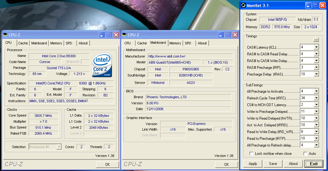
We were able to reach a final benchmark stable setting of 7x515 FSB resulting in a clock speed of 3605MHz. The board was capable of running up to 7x525 FSB but would consistently fail our Dual Prime95 test, although it passed all our game and synthetic benchmarks. We settled on the 7x515 FSB setting and set our VCore to an acceptable 1.4850V with Vdroop being around .02V during load testing. We were able to operate our GEIL memory at 4-4-4-12 at 2.4V with these settings.
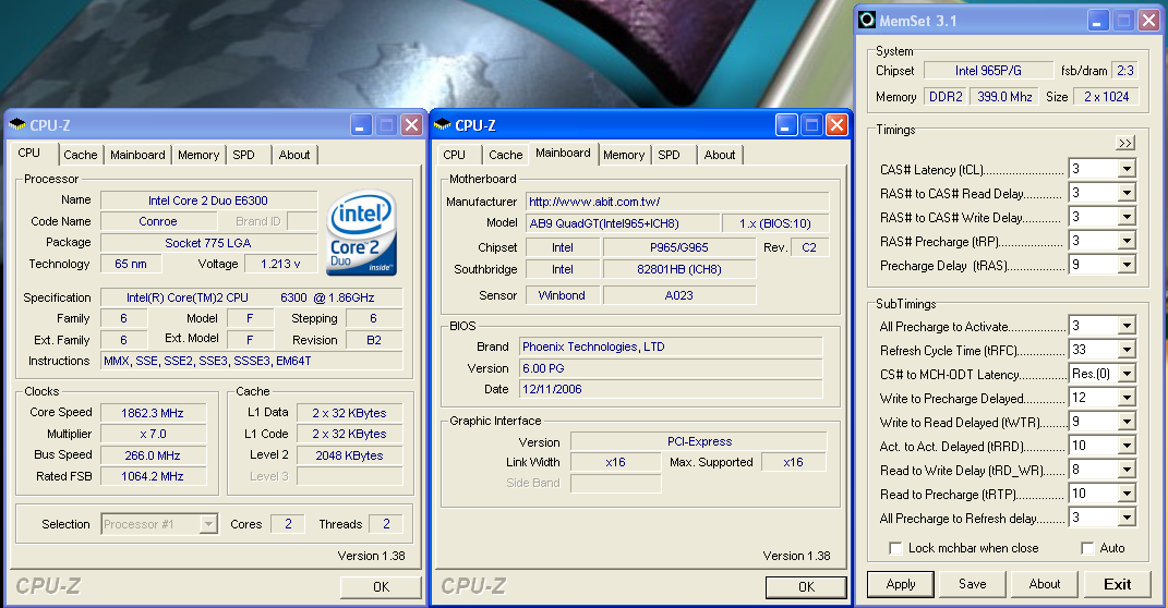
The BIOS allows you to manipulate the MCH strap and memory speeds resulting in a wide variety of performance options based on your components. The current BIOS allows you to stay in the 1067 strap up to the 525FSB ceiling with our E6300 and E6400 chips, and this allows for some incredible memory and system performance at the higher FSB settings. Our E6600 has hit 7x550FSB in initial testing at this time. Our board was extremely stable throughout testing although we noticed the requirement for slightly higher memory voltages at the upper FSB rates due to the tight sub-timings. During overclocking we generally found that at 7x400 and above with our E6300 and the memory set at a 1:1 ratio (800 DDR2) that 4-4-4 timings were up to 7% faster in our benchmarks than forcing the memory latencies to 3-3-3 as the sub-timings were set tighter resulting in improved throughput.
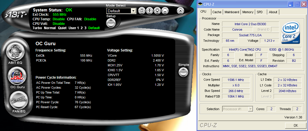
One minor issue we noticed with µGuru is that any setting over the 525FSB limit at this time would still result in the board be able to POST and boot into XP while generating FSB and clock rates that were not real. In our example we set the board to 6x555FSB. It would POST and display 6x555 along with the corresponding memory speed, and once in Windows the µGuru utility would show the same BIOS settings and allow changes to it. However, the system actually would default to the base 266FSB speed with memory at the base settings also.
Memory Stress Testing
We take a look now at seeing how well our GEIL PC2-6400 memory operates in this board in both two and four DIMM testing. The screenshot above shows the actual memory settings used in our benchmark tests of the board. We do not modify the memory timings beyond the four major settings in our charts. The balance of memory settings are implemented automatically via the BIOS. abit implements slightly tighter memory and MCH timings than some of the other P965 boards we have tested.
We were able to set our timings to 3-3-3-9 by increasing the memory voltage to 2.20V with our GEIL memory. We were able to hold these timings up to DDR2-880 on this board before switching over to timings of 4-4-4-12 up to DDR2-1030 at 1:1 timings. We then switched to 5-5-5-15 timings at a 7x465 with a 4:5 ratio that resulted in a maximum stable memory speed of DDR2-1163. We tried out our Corsair Dominator PC-8888 and OCZ Flex XT memory but could not get the board stable at memory speeds greater than DDR2-1163.
Our settings of 3-4-4-12 at 2.275V were not quite as good as our ASUS P5B-E 1.02G settings of 3-4-3-10, but due to fairly tight memory timings elsewhere the benchmark results were actually better. We were able to keep this setting up to DDR2-860 before switching over to 4-4-4-12 settings that held stable until we reached DDR2-960 during our overclocking tests. The board was able to handle settings of 5-4-4-12 up to DDR2-1010. Our final settings of 5-5-4-15 at DDR2-1030 required a voltage increase to 2.325V.
| abit AB9 QuadGT Overclocking Testbed |
|
| Processor: | Intel Core 2 Duo E6300 Dual Core, 1.86GHz, 2MB Unified Cache 1066FSB, 7x Multiplier |
| CPU Voltage: | 1.4850V (default 1.3250V) |
| Cooling: | Tuniq Tower 120 |
| Power Supply: | OCZ GameXStream 700W |
| Memory: | GeIL PC2-6400 800MHz Plus (2x1GB - GX22GB6400PDC) (Micron Memory Chips) |
| Video Cards: | 1 x MSI X1950XTX |
| Hard Drive: | Seagate 320GB 7200RPM SATA2 16MB Buffer |
| Optical Drive: | Sony 18X AW-Q170A-B2 |
| Case: | Cooler Master CM Stacker 830 |
| Maximum CPU OC: | 515x7 (4-4-4-12, 1:1, 2.400V), CPU 1.4850V 3605MHz (+93%) |
| . | |
 |
| Click to enlarge |
We were able to reach a final benchmark stable setting of 7x515 FSB resulting in a clock speed of 3605MHz. The board was capable of running up to 7x525 FSB but would consistently fail our Dual Prime95 test, although it passed all our game and synthetic benchmarks. We settled on the 7x515 FSB setting and set our VCore to an acceptable 1.4850V with Vdroop being around .02V during load testing. We were able to operate our GEIL memory at 4-4-4-12 at 2.4V with these settings.
The BIOS allows you to manipulate the MCH strap and memory speeds resulting in a wide variety of performance options based on your components. The current BIOS allows you to stay in the 1067 strap up to the 525FSB ceiling with our E6300 and E6400 chips, and this allows for some incredible memory and system performance at the higher FSB settings. Our E6600 has hit 7x550FSB in initial testing at this time. Our board was extremely stable throughout testing although we noticed the requirement for slightly higher memory voltages at the upper FSB rates due to the tight sub-timings. During overclocking we generally found that at 7x400 and above with our E6300 and the memory set at a 1:1 ratio (800 DDR2) that 4-4-4 timings were up to 7% faster in our benchmarks than forcing the memory latencies to 3-3-3 as the sub-timings were set tighter resulting in improved throughput.
 |
| Click to enlarge |
One minor issue we noticed with µGuru is that any setting over the 525FSB limit at this time would still result in the board be able to POST and boot into XP while generating FSB and clock rates that were not real. In our example we set the board to 6x555FSB. It would POST and display 6x555 along with the corresponding memory speed, and once in Windows the µGuru utility would show the same BIOS settings and allow changes to it. However, the system actually would default to the base 266FSB speed with memory at the base settings also.
Memory Stress Testing
 |
| Click to enlarge |
We take a look now at seeing how well our GEIL PC2-6400 memory operates in this board in both two and four DIMM testing. The screenshot above shows the actual memory settings used in our benchmark tests of the board. We do not modify the memory timings beyond the four major settings in our charts. The balance of memory settings are implemented automatically via the BIOS. abit implements slightly tighter memory and MCH timings than some of the other P965 boards we have tested.
| abit AB9 QuadGT Stable DDR2-800 Timings - 2 DIMMs (2/4 slots populated - 1 Dual-Channel Bank) |
|
| Clock Speed: | 800MHz |
| CAS Latency: | 3 |
| RAS to CAS Delay: | 3 |
| RAS Precharge: | 3 |
| RAS Cycle Time: | 9 |
| Voltage: | 2.20V |
We were able to set our timings to 3-3-3-9 by increasing the memory voltage to 2.20V with our GEIL memory. We were able to hold these timings up to DDR2-880 on this board before switching over to timings of 4-4-4-12 up to DDR2-1030 at 1:1 timings. We then switched to 5-5-5-15 timings at a 7x465 with a 4:5 ratio that resulted in a maximum stable memory speed of DDR2-1163. We tried out our Corsair Dominator PC-8888 and OCZ Flex XT memory but could not get the board stable at memory speeds greater than DDR2-1163.
| abit AB9 QuadGT Stable DDR2-800 Timings - 4 DIMMs (4/4 slots populated - 2 Dual-Channel Bank) |
|
| Clock Speed: | 800MHz |
| CAS Latency: | 3 |
| RAS to CAS Delay: | 4 |
| RAS Precharge: | 4 |
| RAS Cycle Time: | 12 |
| Voltage: | 2.275V |
Our settings of 3-4-4-12 at 2.275V were not quite as good as our ASUS P5B-E 1.02G settings of 3-4-3-10, but due to fairly tight memory timings elsewhere the benchmark results were actually better. We were able to keep this setting up to DDR2-860 before switching over to 4-4-4-12 settings that held stable until we reached DDR2-960 during our overclocking tests. The board was able to handle settings of 5-4-4-12 up to DDR2-1010. Our final settings of 5-5-4-15 at DDR2-1030 required a voltage increase to 2.325V.


41 Comments
View All Comments
Operandi - Wednesday, January 24, 2007 - link
Excellent.Talcite - Monday, January 22, 2007 - link
Do you guys mean 'Final Impressions' on the last page of the article?Gary Key - Monday, January 22, 2007 - link
It was First Impressions, slip of the tongue until we get the next BIOS release. ;)mechBgon - Monday, January 22, 2007 - link
Hey Gary, I think you got a typo:You meant "noting," not "nothing," right?
JarredWalton - Monday, January 22, 2007 - link
That was my fault, and it's what happens when you edit at 3 AM (and use voice recognition). Anyway, it's fixed, thanks.sprockkets - Monday, January 22, 2007 - link
Intel has such a good processor, then messes up on the IDE. I would gladly make a computer around such a chip, but the nForce 6150 and AMD/Ati chipset is much more compelling, and since my customer needs IDE anyhow, AMD wins.MadAd - Tuesday, January 23, 2007 - link
Its taken all this time to get rid of the parallel port yet the much more used IDE (which should have the same kind of legacy lifespan) is out the door in a flash.If I had a tin foil hat id be shouting conspiracy theory and wondering which one of the storage majors paid Intel off to pull a stunt like that.
Stele - Monday, January 22, 2007 - link
Oh no, that misnomer strikes again... capacitors which use solid aluminium electrolyte are properly called "solid aluminium electrolyte" or at least "solid aluminium"... there are no "solid state" capacitors since, in electronic parlance "solid state" is traditionally used to describe circuits that do not use vacuum tubes (electron flows in solid materials - the semiconductors within ICs - rather than vacuum/empty spaces such as in tubes).
It's a minor point on the face of it, but Anandtech is well-respected throughout the IT community; hence a mistake or misconception could potentially reach and misinform a great deal of readers (and even writers) out there. :)
JarredWalton - Monday, January 22, 2007 - link
Changed - not all of us are electronics experts. Solid state or solid electrolyte - is there a difference to the laymen of the world? ;)Stele - Monday, January 22, 2007 - link
Oh no, no, didn't mean it in any negative way; I understand that, so was just contributing what little I can to help keep Anandtech at the top :P
You're probably quite right that the layman may not know the difference, and indeed they likely wouldn't care either way anyway. The ones we're worried about are those that are just entering the technical arena and/or are in their formative, learning stages... wouldn't want them to start on the wrong footing and spread the misstep when they in turn teach others ;)