Intel P965: Mid-Range Performance Sector Roundup
by Gary Key on October 20, 2006 9:00 PM EST- Posted in
- Motherboards
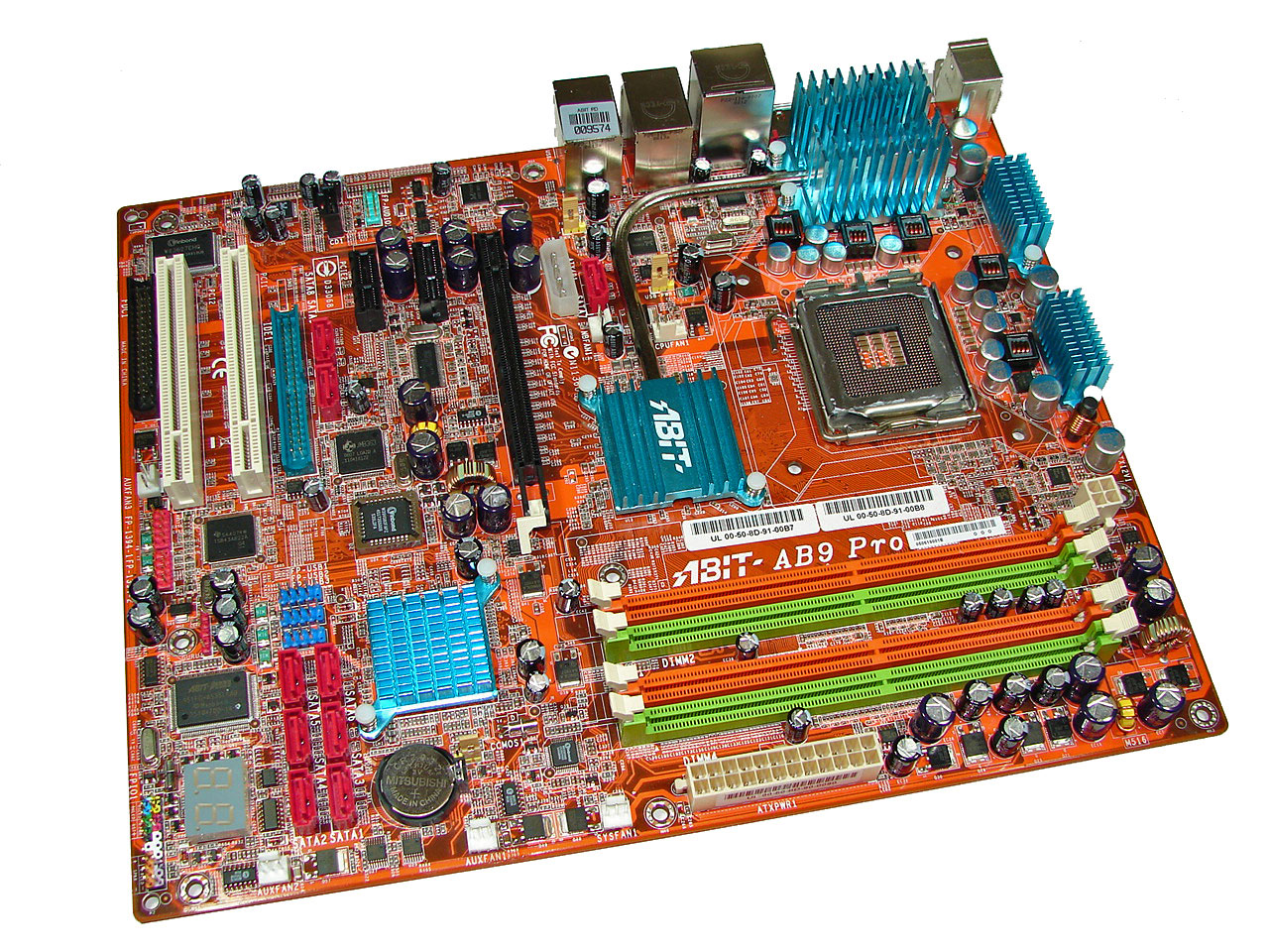
Abit AB9 Pro: Board Layout and Features
Abit designed a board that has one of the more interesting layouts we have seen in a long time. While the board was very easy to install in our mid-size ATX case we did have some issues with utilizing our Optical drive in the top bay due to the location of the JMicron powered IDE port that is located in between the number two PCI Express x1 slot and the number one PCI slot. There are six fan headers on the board that can be controlled by the µGuru Windows utility. The Abit board features an excellent five-phase voltage regulator power design with high quality capacitors located in each major component section of the board that yielded superb stability.
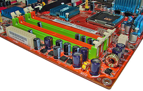
The DIMM module slots' color coordination is correct for dual channel setup based upon the premise of installing DIMMs in the same colored slots for dual-channel operation. The memory modules are easy to install with a full size video card placed in the first PCI Express x16 slot. The 24-pin ATX power connector is located along the edge of the board along with a series of capacitors for the memory modules. Abit places the four-pin 12v auxiliary power connector at the top of the first memory module but completely out of the way of aftermarket cooling solutions we utilized.
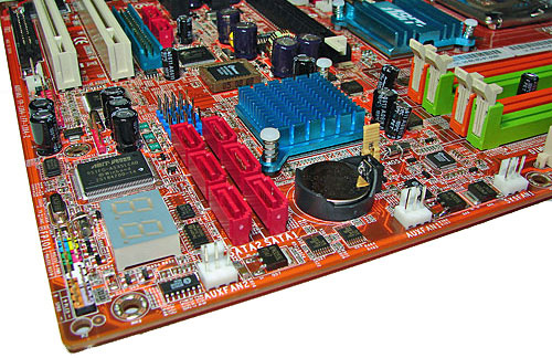
The six Intel ICH8R SATA ports are color coded red and are conveniently located to the left of the ICH8R Southbridge and battery. The SATA ports feature the newer clamp and latch design. We found the positioning of the SATA ports to be excellent when utilizing either the PCI-E x1 or PCI 2.3 slots. The ICH8R is passively cooled and remained cool to the touch throughout testing.
The first three of five auxiliary fan connectors are located at the bottom edge of the board. The clear CMOS jumper is color coded yellow and is located in between the battery and ICH8R chipset. The CP80P post port debug LED, chassis panel, µGuru chipset, and red 1394a connectors are located along the left edge of the board. The blue USB 2.0 connectors are located above the SATA ports.
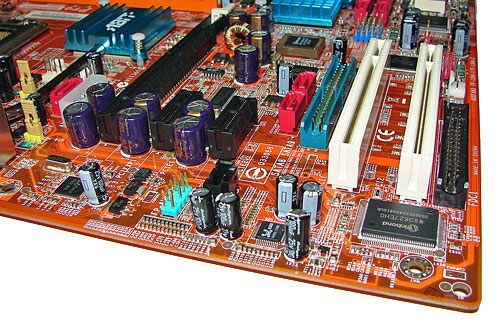
The board comes with (1) physical PCI Express x16 connector, (2) PCI Express x1 connectors, and (2) PCI 2.3 connectors. The layout of this design offers a very good balance of expansion slots for a mainstream board while providing excellent clearance space for graphics card utilization. However, the layout in this area is very unusual if not a bit chaotic. Our main issue is the location of the floppy drive connector at the bottom of the board along with the JMicron JMB363 IDE and SATA ports being sandwiched in between the PCI-E and PCI slots in the middle of the board.
The four-pin Molex power connector that will be required for future GPU products is located above the PCI-E x16 slot along with the Silicon Image 3132 SATA port. Abit informed us some of the unusual port locations were predicated upon ensuring proper power delivery, stability, and trace layouts based upon the capacitor locations. However, we still have to wonder if some of these layout choices were design gaffe that accidentally made it into production.
Returning to the CPU socket area, we find an ample amount of room for alternative cooling solutions. We utilized the stock heatsink/fan in our normal testing but also verified a couple of larger Socket-775 cooling solutions such as the Tuniq Tower 120 would fit in this area during our overclocking tests.
The Intel P965 MCH chipset is passively cooled with a low rise heatsink unit that did not interfere with any installed peripherals. This heatsink is part of the Abit Silent OTES technology that includes a heatpipe system and additional passive cooling for the VRM components. This system kept the MCH cool enough that additional chipset voltage was not a factor in our overclocking tests.
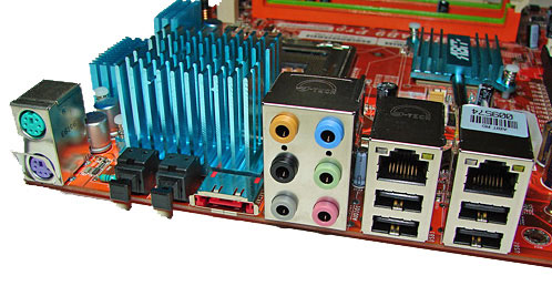
The rear panel contains the standard PS/2 mouse and keyboard ports, LAN ports, and 4 USB ports. The LAN (RJ-45) ports have two LED indicators representing Activity and Speed of the connection through the Realtek RTL8168 Gigabit PCI-E chipset. The audio panel consists of 6 ports that can be configured for 2, 4, 6, and 8-channel audio connections for the Realtek ALC 882D HD codec. The panel also consists of two S/PDIF (optical in/optical out) ports, and an external SATA 3Gb/s port via the Silicon Image 3132 chipset. All in all, Abit included an excellent combination of ports although another two USB ports would have been handy for additional peripherals.
 |
| Click to enlarge |
Abit designed a board that has one of the more interesting layouts we have seen in a long time. While the board was very easy to install in our mid-size ATX case we did have some issues with utilizing our Optical drive in the top bay due to the location of the JMicron powered IDE port that is located in between the number two PCI Express x1 slot and the number one PCI slot. There are six fan headers on the board that can be controlled by the µGuru Windows utility. The Abit board features an excellent five-phase voltage regulator power design with high quality capacitors located in each major component section of the board that yielded superb stability.
The DIMM module slots' color coordination is correct for dual channel setup based upon the premise of installing DIMMs in the same colored slots for dual-channel operation. The memory modules are easy to install with a full size video card placed in the first PCI Express x16 slot. The 24-pin ATX power connector is located along the edge of the board along with a series of capacitors for the memory modules. Abit places the four-pin 12v auxiliary power connector at the top of the first memory module but completely out of the way of aftermarket cooling solutions we utilized.
The six Intel ICH8R SATA ports are color coded red and are conveniently located to the left of the ICH8R Southbridge and battery. The SATA ports feature the newer clamp and latch design. We found the positioning of the SATA ports to be excellent when utilizing either the PCI-E x1 or PCI 2.3 slots. The ICH8R is passively cooled and remained cool to the touch throughout testing.
The first three of five auxiliary fan connectors are located at the bottom edge of the board. The clear CMOS jumper is color coded yellow and is located in between the battery and ICH8R chipset. The CP80P post port debug LED, chassis panel, µGuru chipset, and red 1394a connectors are located along the left edge of the board. The blue USB 2.0 connectors are located above the SATA ports.
The board comes with (1) physical PCI Express x16 connector, (2) PCI Express x1 connectors, and (2) PCI 2.3 connectors. The layout of this design offers a very good balance of expansion slots for a mainstream board while providing excellent clearance space for graphics card utilization. However, the layout in this area is very unusual if not a bit chaotic. Our main issue is the location of the floppy drive connector at the bottom of the board along with the JMicron JMB363 IDE and SATA ports being sandwiched in between the PCI-E and PCI slots in the middle of the board.
The four-pin Molex power connector that will be required for future GPU products is located above the PCI-E x16 slot along with the Silicon Image 3132 SATA port. Abit informed us some of the unusual port locations were predicated upon ensuring proper power delivery, stability, and trace layouts based upon the capacitor locations. However, we still have to wonder if some of these layout choices were design gaffe that accidentally made it into production.
 |
| Click to enlarge |
Returning to the CPU socket area, we find an ample amount of room for alternative cooling solutions. We utilized the stock heatsink/fan in our normal testing but also verified a couple of larger Socket-775 cooling solutions such as the Tuniq Tower 120 would fit in this area during our overclocking tests.
The Intel P965 MCH chipset is passively cooled with a low rise heatsink unit that did not interfere with any installed peripherals. This heatsink is part of the Abit Silent OTES technology that includes a heatpipe system and additional passive cooling for the VRM components. This system kept the MCH cool enough that additional chipset voltage was not a factor in our overclocking tests.
The rear panel contains the standard PS/2 mouse and keyboard ports, LAN ports, and 4 USB ports. The LAN (RJ-45) ports have two LED indicators representing Activity and Speed of the connection through the Realtek RTL8168 Gigabit PCI-E chipset. The audio panel consists of 6 ports that can be configured for 2, 4, 6, and 8-channel audio connections for the Realtek ALC 882D HD codec. The panel also consists of two S/PDIF (optical in/optical out) ports, and an external SATA 3Gb/s port via the Silicon Image 3132 chipset. All in all, Abit included an excellent combination of ports although another two USB ports would have been handy for additional peripherals.


62 Comments
View All Comments
zjohnr - Tuesday, November 7, 2006 - link
In all the features tables for the motherboards in this article the PCI slots are listed as being PCI v2.3. However, looking at the pictures for the boards, the slots have PCI v2.2 keying. I think the entry in the features tables is wrong. (Is it?)Patsoe - Saturday, October 28, 2006 - link
Seeing all the trouble with the P965 - especially with the non-intel p-ata controller and with the ich8r - I'd be inclined to get a Core2-ready i945P board with ICH7R instead. Would that be a sane idea?BadThad - Tuesday, October 24, 2006 - link
Is the v1.02G Asus P5B-E using all solid capacitors? I read a press release stating that Asus was releasing the "P4B-E Plus" version with all solid caps. Rumor says the "Plus" version will not be sold in the USA.....arrgggggg. Tell me that's not true. I want the solid caps for long-term reliability. I'm wondering if our "Plus" is actually the v1.02G?Thanks
Gary Key - Tuesday, October 24, 2006 - link
The 1.01G and 1.02G boards are exactly the same except for a PLL controller. Asus stills states the P5B-Plus will not be imported into the States but you never know.keithke - Monday, October 23, 2006 - link
I was interested to hear you used this Scythe Infinity Air Cooler as I was going to do the same. Were there any issues with the Northbridge heatsink sitting so close? Or did it just plop right in with no spacing issues?Thx
Keith
Gary Key - Tuesday, October 24, 2006 - link
No issues with the Inifinity on all four corners. It is a close fit but it works fine with the enclosed fan.SniperWulf - Monday, October 23, 2006 - link
Hey guys,Did you have any strange anomolies with the X-fi on the DS3 while overclocked? When I was using that board with the F6 bios, I'd have to reboot like 3-4 times before windows would properly detect it. I eventually grew tired of it and bought a P5B-D so I haven't had a chance to try F7 with it.
Gary Key - Monday, October 23, 2006 - link
I did not have any issues with the X-FI on the DS3 when it was overclocked. The F5 and F6 BIOS releases were not X-FI friendly where F4 was perfect. F7 is working for some and not others, I did not have an issue with it. F8 will fix it for good.schlumpfi106 - Monday, October 23, 2006 - link
Im a little bit disappointed that there are so few informations about the cooling/silencing-related capabilitites of the boards. I would like to know how many fans can be connected, if the connectors are 3- or 4-pin, and if there is a way to control the fan speeds (preferably via SpeedFan). I don't care about a one-percent performance difference. My first priority is a reasonably silent system.goinginstyle - Monday, October 23, 2006 - link
He mentioned the number of fan headers on each board and even added a couple of comments on the ones that did not work right. In the features section there was a statement about whether the included utility worked or not. Sure he did not say anything about SpeedFan but how far do you want a guy to go after 26 pages? Also, if you click on the Enlarge picture on the boards you can clearly make out whether the fan headers are 3 or 4 pin.