AMD Thunderbird & Duron Overclocking Revealed
by Anand Lal Shimpi on July 19, 2000 3:54 AM EST- Posted in
- Guides
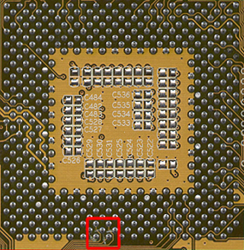
Now that we know what our ‘OVERRIDE’ pins are actually doing, the question still remains, how do we set the FID pins? This is actually the easy part since we already know what pins on the Thunderbird/Duron correspond to the FID pins; as we mentioned earlier they are: W1, W3, Y1 and Y3.
In order for us to take control of the FID settings, we must first remove the CPU’s ability to tell the North Bridge what clock multiplier it wants. We already have control over the BP_FID pins as we proved with our previous experiment, so if we can gain control over the FID pins we should be good to go.
As Hiroji, a Duron owner and hardware enthusiast, documented on his site and as we confirmed, the FIC AZ-11 again turns out to be the perfect candidate for experimentation since the traces going from the four FID pins are present on the bottom layer of the PCB. They could very well be on the top layer or on the middle layers depending on the board design, luckily they are very easily accessible on the AZ-11, the board that we have been experimenting with.
So what do we do with those four traces coming from the FID pins? Well, we have to prevent the CPU from telling the North Bridge what clock multiplier it wants, so we have to physically cut those traces (it sounds bad but it’s much better than removing the pins from the CPU).
Using a lot of patience and an exact-o knife we simply cut the four traces as you can see in picture below:
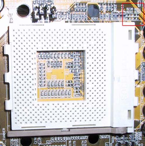
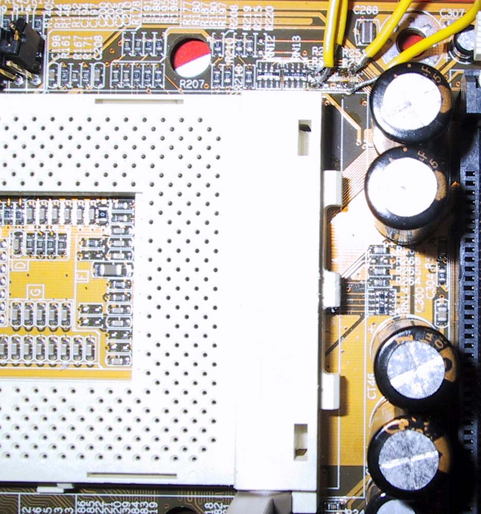
The final piece of the puzzle is creating our own way of controlling the FID signals that are sent to the North Bridge and this last bit of information is once again provided by Hiroji who discovered that the four resistor positions (they don’t actually hold resistors but are labeled as such) on the AZ-11: R237, R238, R250 & R251 actually control the FID signal sent to the North Bridge.
So, after picking up an 8 station dip switch (we only needed to use four stations but our local store was all out of 4 station parts) we went to work soldering our modified AZ-11 yet again. Below you can see the specifics of exactly what positions correspond to what FID pins (the connections were made on the four outermost contact points):


0 Comments
View All Comments