AMD Thunderbird & Duron Overclocking Revealed
by Anand Lal Shimpi on July 19, 2000 3:54 AM EST- Posted in
- Guides
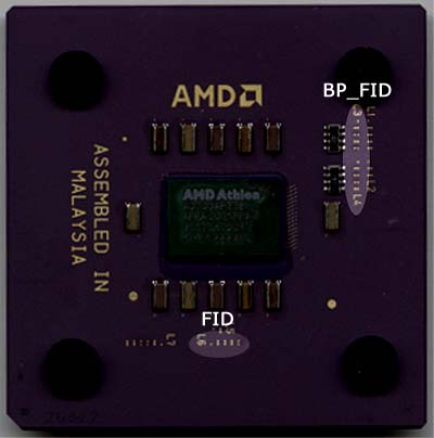
The next thing we had to prove was that the BP_FID settings for the range of acceptable clock multipliers were the same as the FID settings for the multipliers since we were originally manipulating the jumpers based on the assumption that they controlled the FID pins of the CPU.
For this we went to Tom's Hardware's recent publication of the Golden Bridge settings for those of you that wanted to physically modify the “Golden Bridges” on your CPU in order to change the clock multiplier. The chart on Page 4 of his guide documents all of the FID and the BP_FID settings, but if you’ll notice there are only four FID “Golden Bridges” whereas there are twice as many (eight) “Golden Bridges” for the BP_FID settings.
But wait a minute, we just said that the four ‘OVERRIDE’ jumpers on the AZ-11 corresponded to the BP_FID pins, but in Tom’s table there are eight “Golden Bridges” that correspond to the BP_FID pins. So what’s going on?
Instead of simply being connected or disconnected like the FID pins, the BP_FID pins can either be set to Ground (GND) or be pulled up to 2.0V. Because of this characteristic of the BP_FID pins, they require two “Golden Bridges” to set one pin thus explaining the eight “Golden Bridges” that correspond to the four BP_FID pins and this also explains why our ‘OVERRIDE’ jumpers are three pin jumpers that have two settings (1-2 or 2-3) instead of simply two pin jumpers that are either capped or left un-connected.
But let’s get back to proving that the BP_FID settings were the same as the FID settings. If we assume that having the first “Golden Bridge” in a set of two connected and the second left unconnected corresponds to a setting of 1 and vise versa, you’ll notice that the FID and BP_FID settings on Tom's chart are exactly the same for the same clock multiplier.
If you followed all that then you’ll know what the conclusion is: the four ‘OVERRIDE’ jumpers on the FIC AZ-11 that we soldered on our final board control the four BP_FID pins on the Thunderbird/Duron. More specifically, setting the jumpers to 1-2 results in a setting of Ground and setting them to 2-3 results in a setting of 2.0V in the case of the BP_FID pins.


0 Comments
View All Comments