Abit AT8: µGuru comes to the RD480
by Gary Key on March 10, 2006 12:05 AM EST- Posted in
- Motherboards
Abit AT8: Features
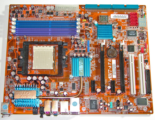
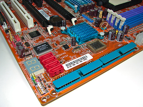
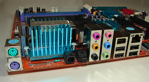
The ULi SATA ports are conveniently located above the number two IDE port connector and to the right of the CP80P post port debug LED. The SATA ports feature the new clamp and latch design, but are not color-coded. The chassis panel is located on the bottom left edge of the board below the CP80P LED. We do miss the power on and reset buttons from previous Abit boards.
The µGuru chipset is located above the ULi SATA ports and independently controls the µGuru functions . The TI TSB43AB22 IEEE 1394 chipset is located above the µGuru chipset. The IEEE 1394 connector is color-coded red and is located directly to the left of the TI IEEE 1394 chipset. The yellow clear CMOS jumper block is a traditional jumper design located to the left of the IEEE 1394 connector and along the edge of the motherboard. The red GURU connector is located below the CMOS jumper and also along the edge of the motherboard.
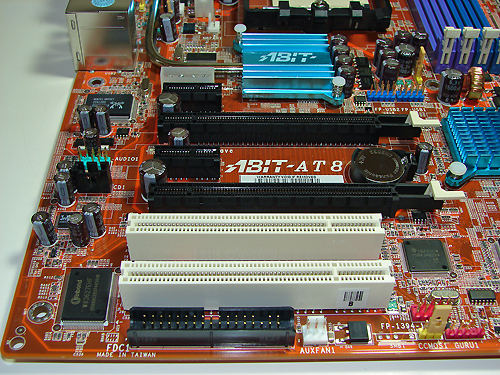
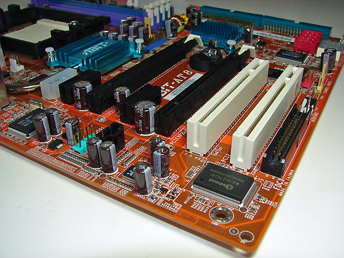
The first PCI Express x1 connector is located below the 4-pin power connector that must be used if two video cards are installed. The first physical PCI Express x16 connector is located next, followed by the second PCI Express x1 connector, second PCI Express x16 connector, and the two PCI 2.3 slots. The floppy drive connector is located below the second PCI slot and is inconveniently located for most case designs. The third of six fan headers located on the board is located to the right of the floppy drive connector.
We did not have any issues installing our ATI X1900XT video cards in the first and second x16 PCI Express slots. These dual slot configuration cards will physically render the second PCI Express x1 and first 32-bit PCI slot useless. We did not have any issues utilizing these slots with video cards containing single slot cooling systems. The first PCI Express x16 connector is considered to be the secondary slot and the second PCI Express x16 connector is considered to be the primary slot. If you utilize one video card, it must be installed in the primary slot. Abit ships a shadow card to use in the secondary slot in single video card configurations, but we found that it was not necessary to use the card. When we installed our EVGA 7800GTX 512MB card in the primary slot, it blocked the first three SATA ports.
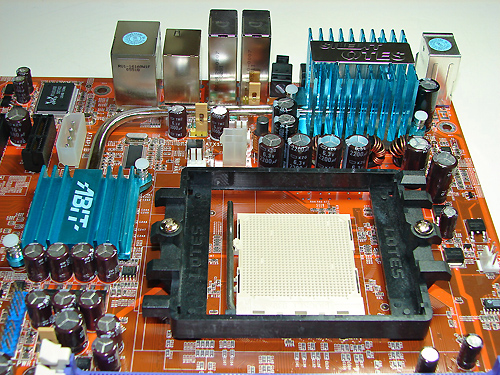
The ATI Crossfire Xpress 200 chipset is passively cooled with a small heat sink unit that did not interfere with any installed peripherals. This unit along with the heatpipe running to the large PVM heat sink kept the chipsets cooled well during overclock testing.
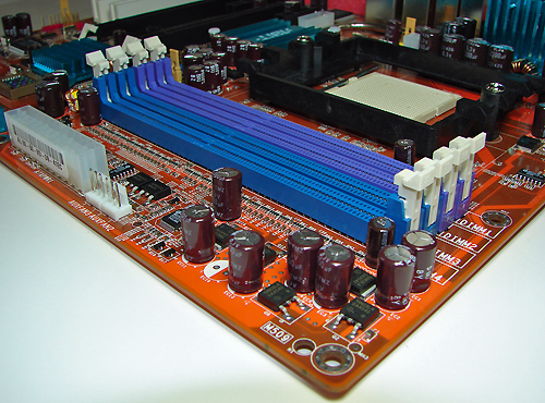
Abit places the ATX12V auxiliary power connector at the top of the CPU socket area. This connector is located in an unusual position and could hamper airflow with cabling that crosses directly over the CPU heat sink/fan; although, we did not have any issues in our case.
The ULi SATA ports are conveniently located above the number two IDE port connector and to the right of the CP80P post port debug LED. The SATA ports feature the new clamp and latch design, but are not color-coded. The chassis panel is located on the bottom left edge of the board below the CP80P LED. We do miss the power on and reset buttons from previous Abit boards.
The µGuru chipset is located above the ULi SATA ports and independently controls the µGuru functions . The TI TSB43AB22 IEEE 1394 chipset is located above the µGuru chipset. The IEEE 1394 connector is color-coded red and is located directly to the left of the TI IEEE 1394 chipset. The yellow clear CMOS jumper block is a traditional jumper design located to the left of the IEEE 1394 connector and along the edge of the motherboard. The red GURU connector is located below the CMOS jumper and also along the edge of the motherboard.
The first PCI Express x1 connector is located below the 4-pin power connector that must be used if two video cards are installed. The first physical PCI Express x16 connector is located next, followed by the second PCI Express x1 connector, second PCI Express x16 connector, and the two PCI 2.3 slots. The floppy drive connector is located below the second PCI slot and is inconveniently located for most case designs. The third of six fan headers located on the board is located to the right of the floppy drive connector.
We did not have any issues installing our ATI X1900XT video cards in the first and second x16 PCI Express slots. These dual slot configuration cards will physically render the second PCI Express x1 and first 32-bit PCI slot useless. We did not have any issues utilizing these slots with video cards containing single slot cooling systems. The first PCI Express x16 connector is considered to be the secondary slot and the second PCI Express x16 connector is considered to be the primary slot. If you utilize one video card, it must be installed in the primary slot. Abit ships a shadow card to use in the secondary slot in single video card configurations, but we found that it was not necessary to use the card. When we installed our EVGA 7800GTX 512MB card in the primary slot, it blocked the first three SATA ports.
The ATI Crossfire Xpress 200 chipset is passively cooled with a small heat sink unit that did not interfere with any installed peripherals. This unit along with the heatpipe running to the large PVM heat sink kept the chipsets cooled well during overclock testing.
Abit places the ATX12V auxiliary power connector at the top of the CPU socket area. This connector is located in an unusual position and could hamper airflow with cabling that crosses directly over the CPU heat sink/fan; although, we did not have any issues in our case.


42 Comments
View All Comments
FireTech - Monday, April 10, 2006 - link
Status Update - Revised 1.1 BiosAbit provided us a revised 1.1 bios tonight (3-9-06) for additional testing and it will be available on Abit's website shortly. We will update the article after our regression testing is completed.
Hi Gary, it would be great if you could please do that promised follow-up review update for the AT8 especially now the AT8 32X is out. It has beeen a while since the initial review and so things should have settled down now or possibly even a new 'beyond 1.1' beta BIOS has been produced for you?
Please update this review and maybe have a follow up on all the Crossfire boards you have reviewed. There seem to be quite a few owners talking on various forums who bought on the strength of these reviews and are relying on you to get things moving on the manufacturer support front...
I'm personally just waiting to see if the AT8 can be the board it was advertised to be before I take the plunge. Why buy into trouble if you don't need to, I've done the 'early adopter' thing too often already?
Gary Key - Monday, July 3, 2006 - link
We are still seeing issues with Infineon based memory that is set to 2-3-2-5 in the SPD, the board will not boot. If your memory utilizes these IC chips, the only choice you is to install some Samsung TCCD, boot the board, manually change the CAS to 2.5, reboot, shutdown, install the other memory, and boot again. Hopefully, Abit will do another bios spin, otherwise, you are left with this hack.Zoomer - Tuesday, March 21, 2006 - link
Wish you could plug abit's use of the 882D more, it seems to be an excellent realtek chipset. It matches the x-fi in the 3d rightmark tests and is competitive with it even in games. Excellent job!Another thing: Could you guys do some objective listening tests to the audio output? Blind A/B switches between the HDA and onboard audio using good quality speakers and/or headphones will be welcome. :)
Gary Key - Friday, March 24, 2006 - link
Our next step in audio testing, besides subjective remarks, will be doing objective audio tests (besides sampling output from RMAA 5.5) on each new codec implemented on a board. We are still deciding how to do this and my personal preference is to provide a download link to a high quality audio output file from each codec tested. These files would be a standardized clip from a music selection, movie scene, and game sequence. The question is if we will receive permission from the involved parties to allow distribution and obviously what choice of equipment to utilize for the audio capture without distorting the file before playback through the on-board codec or discreet card. Something on the list to do besides new creating new benchmarks also....... :)
Zoomer - Saturday, March 25, 2006 - link
Oh sorry, I meant to say subjective blind listening tests. But that might be a good idea too. To avoid licensing issues, you could use public domain music. However, the quality of the client output hardware and the recording method used would taint results.Duplex - Friday, March 24, 2006 - link
A suggestion to develop the audiotest is that you measure 1. the latency from input(ad) to "software" and 2. from input(ad) to "software" to output(da) with or without some well defined effect applied.Realtek: We don't support ASIO & GSIF directly in our driver.
For ASIO, there is an "universal ASIO driver for WDM audio" available on ASIO4ALL. Please refer to http://www.asio4all.com">http://www.asio4all.com. It is free for end-users.
Zoomer - Tuesday, March 21, 2006 - link
If I am reading it correctly, you are saying the primary slot is the 4th from the cpu, or in the middle of the board and will cover 1 pci slot when used.If that is correct, I suspect this will be a deal breaker for many. It effectively transforms the board to having 1 PCI slot or even none at all, and 2 usable but useless pcie slots, 1 1x and another 8x.
Gary Key - Friday, March 24, 2006 - link
Yes, the primary x16 slot is the lower x16 slot on the board. If you use a X1900XT (dual slot card) as an example you will render the PCI slot next to it useless.
Zoomer - Saturday, March 25, 2006 - link
Well, I think it was a bad decision on abit's part. Why leave the top part of the board free while overcrowding the bottom? End users are suffering from these strange board design because of nvidia's SLI now.PS: Yes, I do think SLI is a terribly bad idea.
Operandi - Sunday, March 12, 2006 - link
Excellent review I particularly liked the coverage on the fan control, good work.