The Corsair RM1000x and RM1000i 1000W Power Supply Review
by E. Fylladitakis on September 30, 2015 8:00 AM EST- Posted in
- Cases/Cooling/PSUs
- Corsair
- RM Series
- Corsair Link
The Corsair RM1000i & RM1000x PSU - External Appearance
Physically, the RM1000i and RM1000x are nearly identical to each other. Their chassis is sprayed with a matte black color that is well applied and fingerprint-resistant. Further aesthetic improvements include chamfered side edges and side stickers with the model's number printed on them.
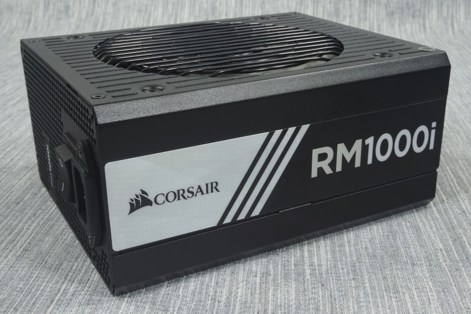
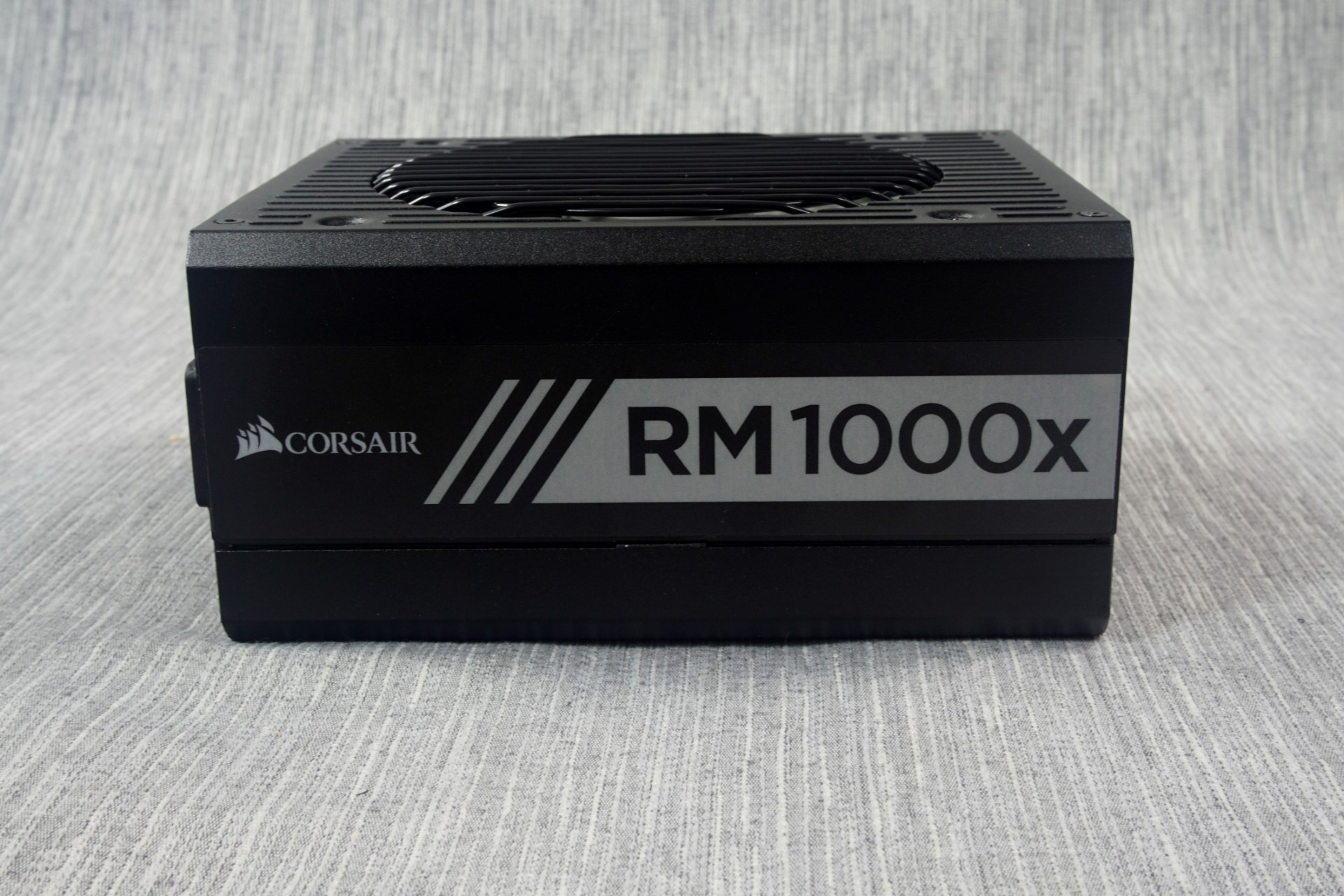
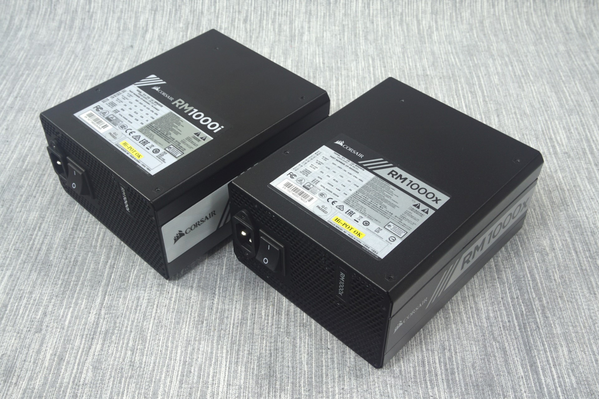
Another sticker can be found at the top of the chassis, with the electrical specifications of the unit. Both models are using the same 180mm long chassis. Note that this chassis is significantly longer than a standard ATX design (140mm) and may not fit into some designs, especially very compact layouts.
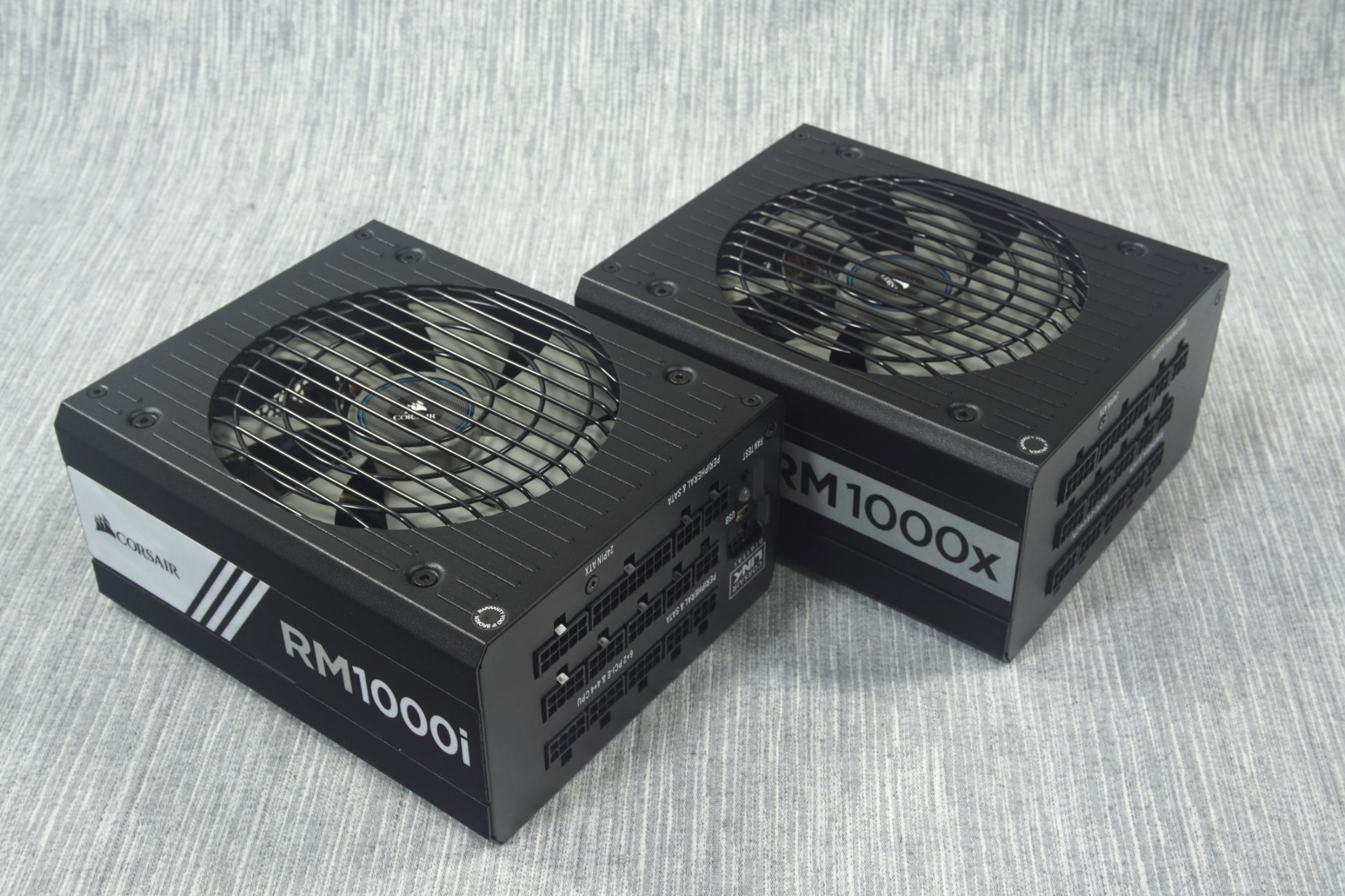
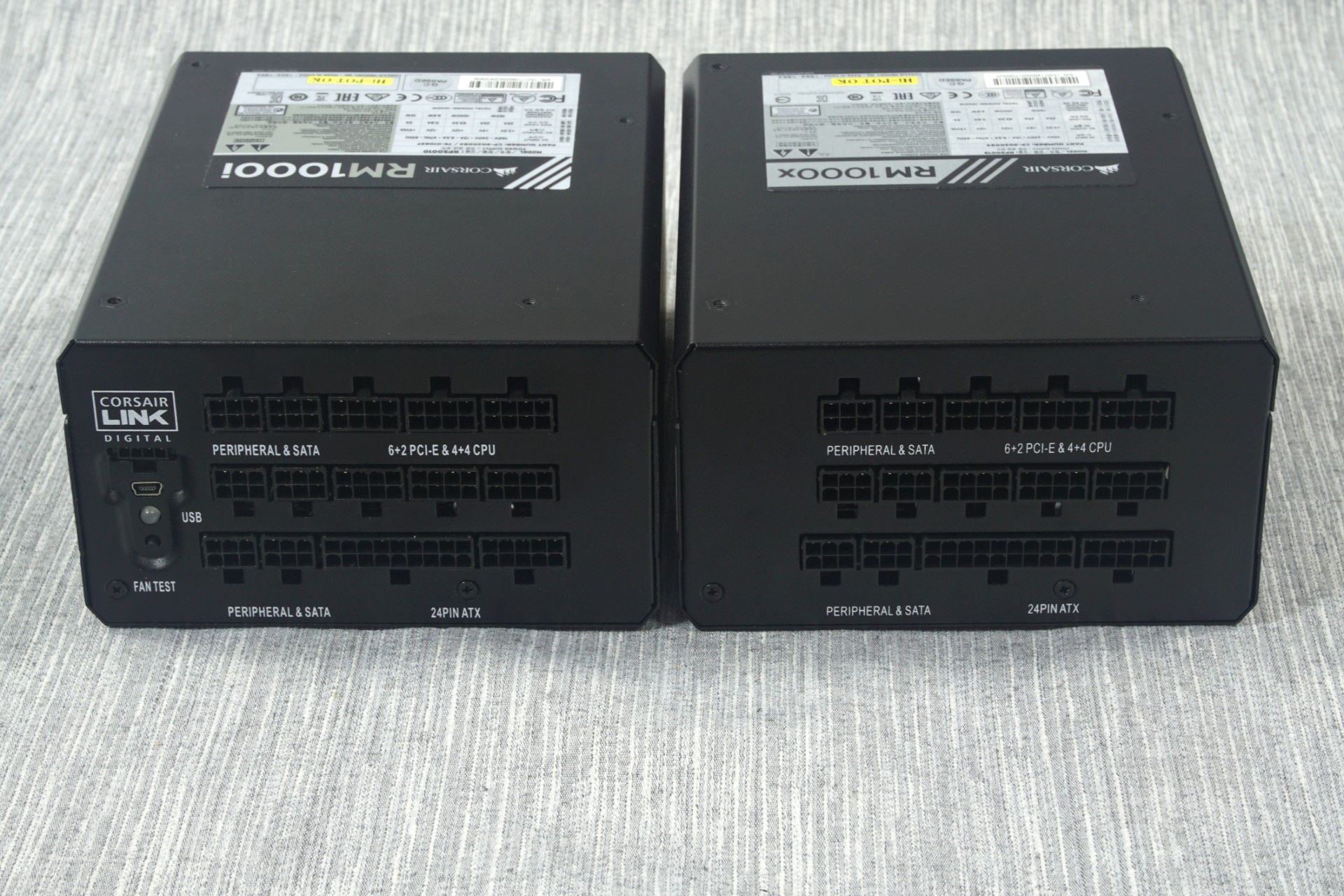
The front of the PSUs are littered with the numerous connectors for the modular cables. The number and type of connectors is identical, with the sole exception that the RM1000x lacks the Corsair Link interface connectors and the test button. There is a very basic legend printed beneath each group of connectors. Both the PCI-Express and the CPU 12V cables use the same connectors, the 6-pin connectors are for the SATA/Molex cables and the split 10+18 connector is for the 24-pin ATX cable.
The Corsair RM1000i & RM1000x PSU - Internal Design
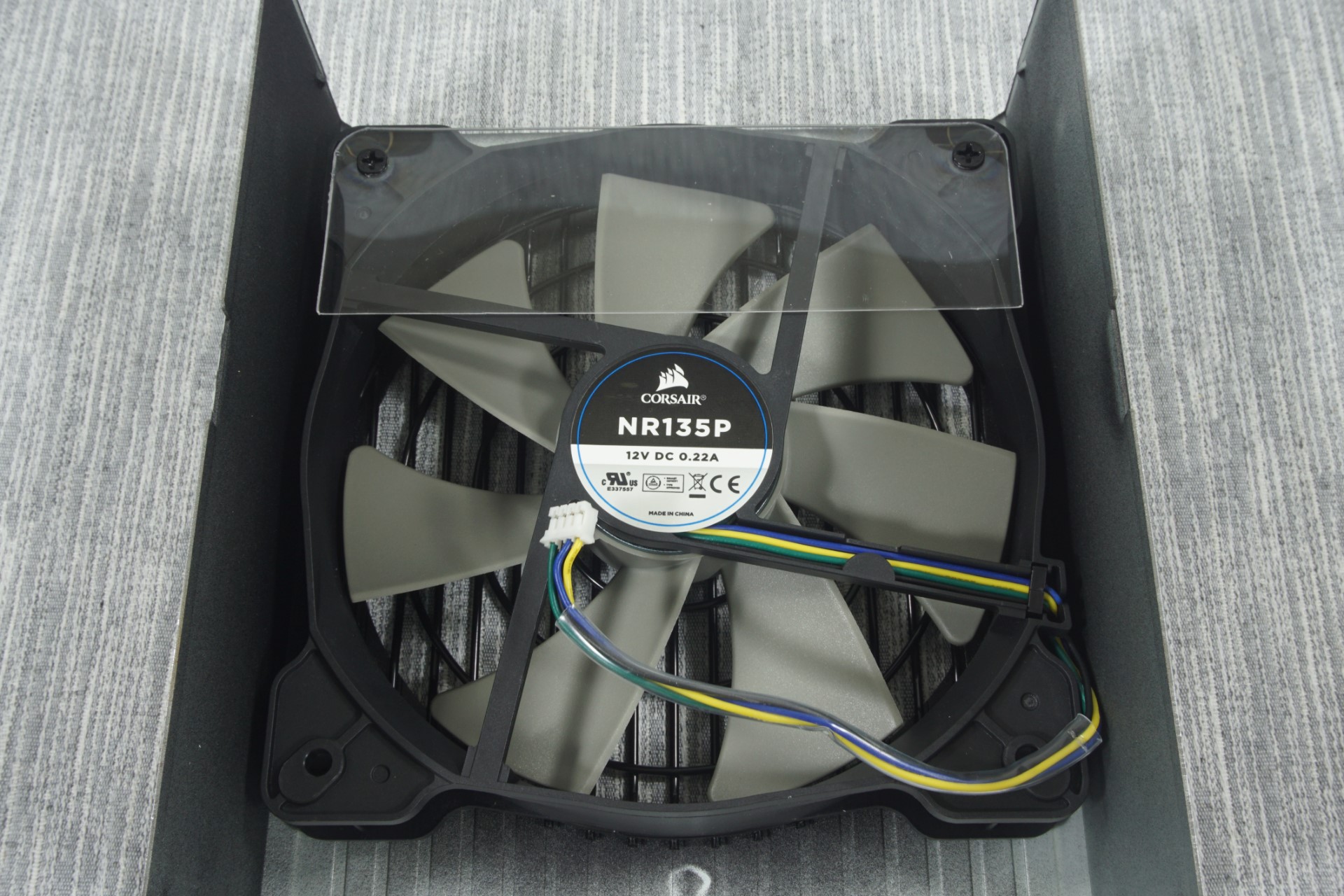
The 135mm fan responsible for the cooling of the RM1000i and the RM1000x is a Corsair NR135P fan. As even the UL certification number points back to Corsair, this technically is Corsair's own unique product and not a re-branded fan, though it's a safe bet that ultimately some hereto-unknown Chinese factory still makes it for them. It has a FDB bearing and a maximum speed of about 1500 RPM. At this point we should note that both of the units feature a "zero-RPM fan mode", meaning that the fan will not start before the load is significant and component temperatures will require active cooling.
Both the RM1000i and the RM1000x are virtually identical on the inside as well, with the mere difference being the RM1000x lacking the circuitry related to the Corsair Link interface. The OEM behind their creation is Channel Well Technologies (CWT) and both units actually are an upgrade of the design that the RM1000 was based upon.
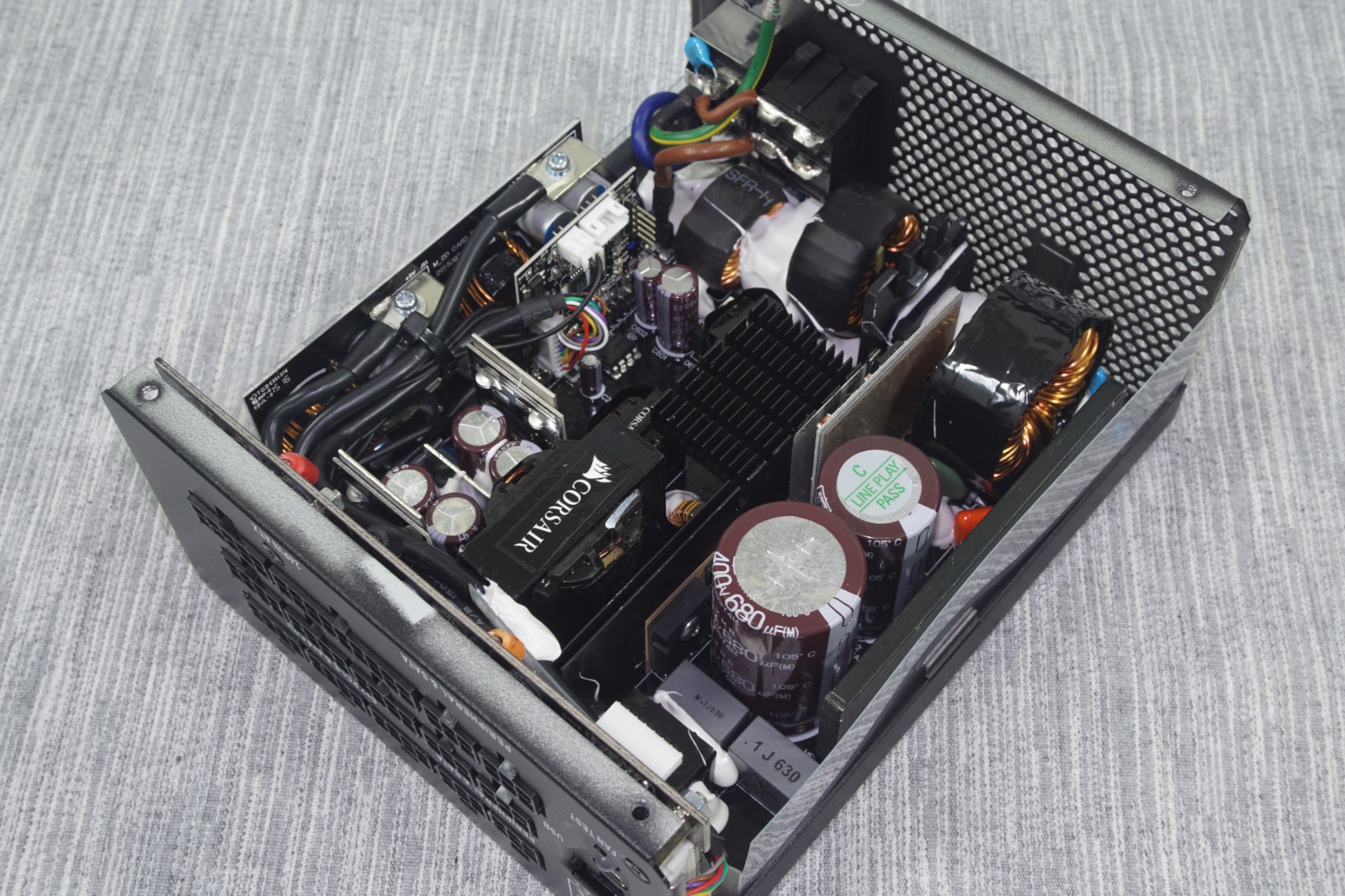
RM1000i (left) & RM1000x (right)
The first notable upgrade is the heatsinks. The heatsinks of the RM1000 were preposterously small for a PSU with that kind of output and rightfully Corsair thought that they would be a good place to start upgrading. Most of their focus was placed on the heatsink cooling the transistors at the primary side of the transformer, which is a huge upgrade over the small solid block of metal we saw in the original RM1000. The heatsink holding the APFC diode and transistors is still a solid block but it is a little longer.
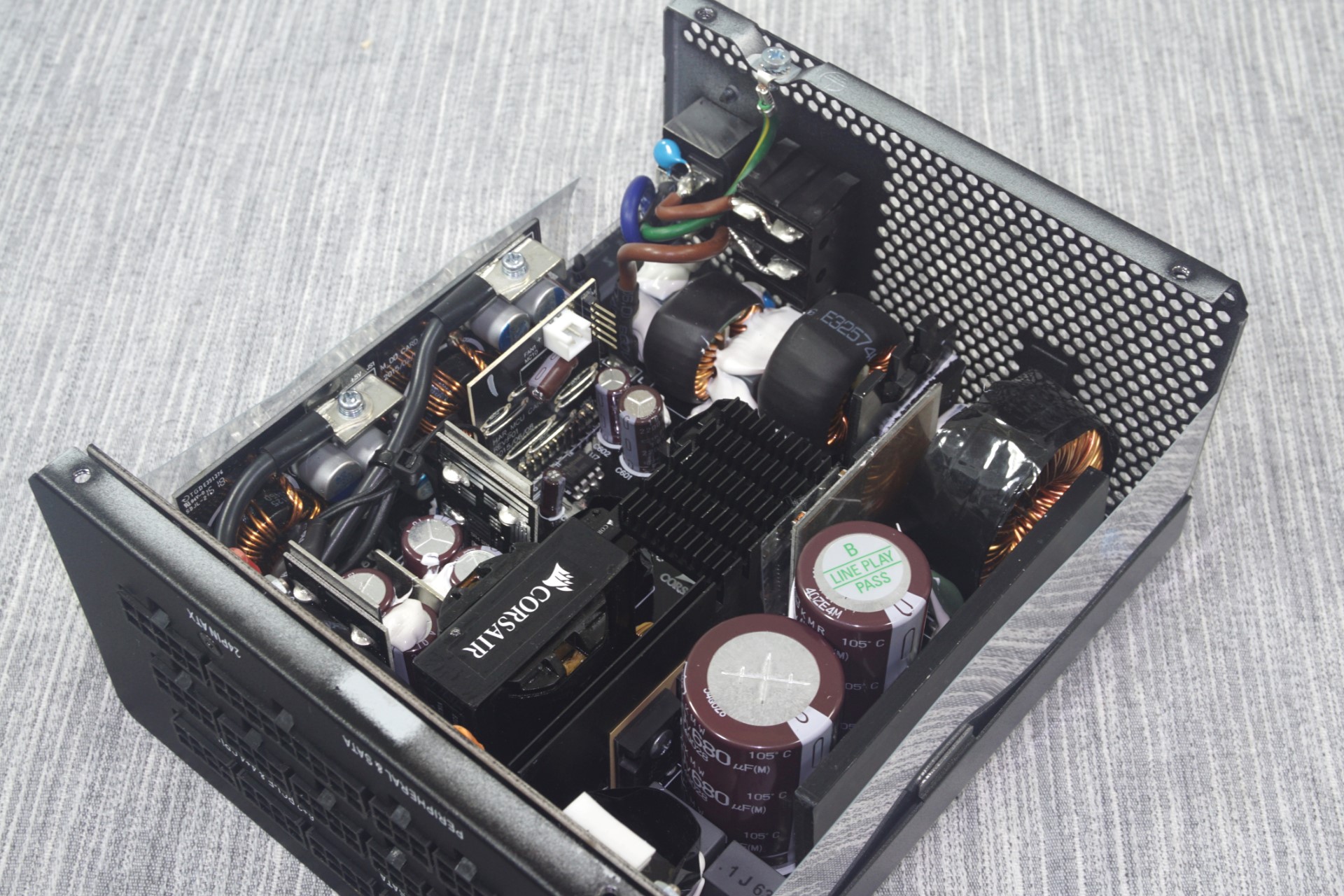
The second upgrade is the sizing and the quality of the components. At the primary side, the APFC capacitors are still supplied by Nippon Chemi-Con but they are one 680μF and one 470μF capacitor, for a whopping total capacitance of 1150μF. The original RM1000 had two 390μF capacitors instead. Note that the capacitors of the RM1000i and the RM1000x may look physically different, but they actually are identical (KMR vs KMW series). Only their physical proportions differ and Corsair may be using either model depending on their availability. All of the secondary side capacitors, electrolytic and polymer alike, are now supplied by Nippon Chemi-Con as well, not TAICON and CapXon.


There are no sizable heatsinks at the secondary side of the transformer. The rectifying MOSFETs are being cooled by small metallic bars, some of which are being used as current distribution bars as well. Corsair is also using a lot of silicon glue throughout the unit, in an effort to enhance its mechanical cohesion. They seem to have placed a particular amount of effort to minimize electromagnetic vibration noise, or "coil whine", by placing a lot of glue on every inductor of the unit. They even wrapped the larger inductors with insulating material.


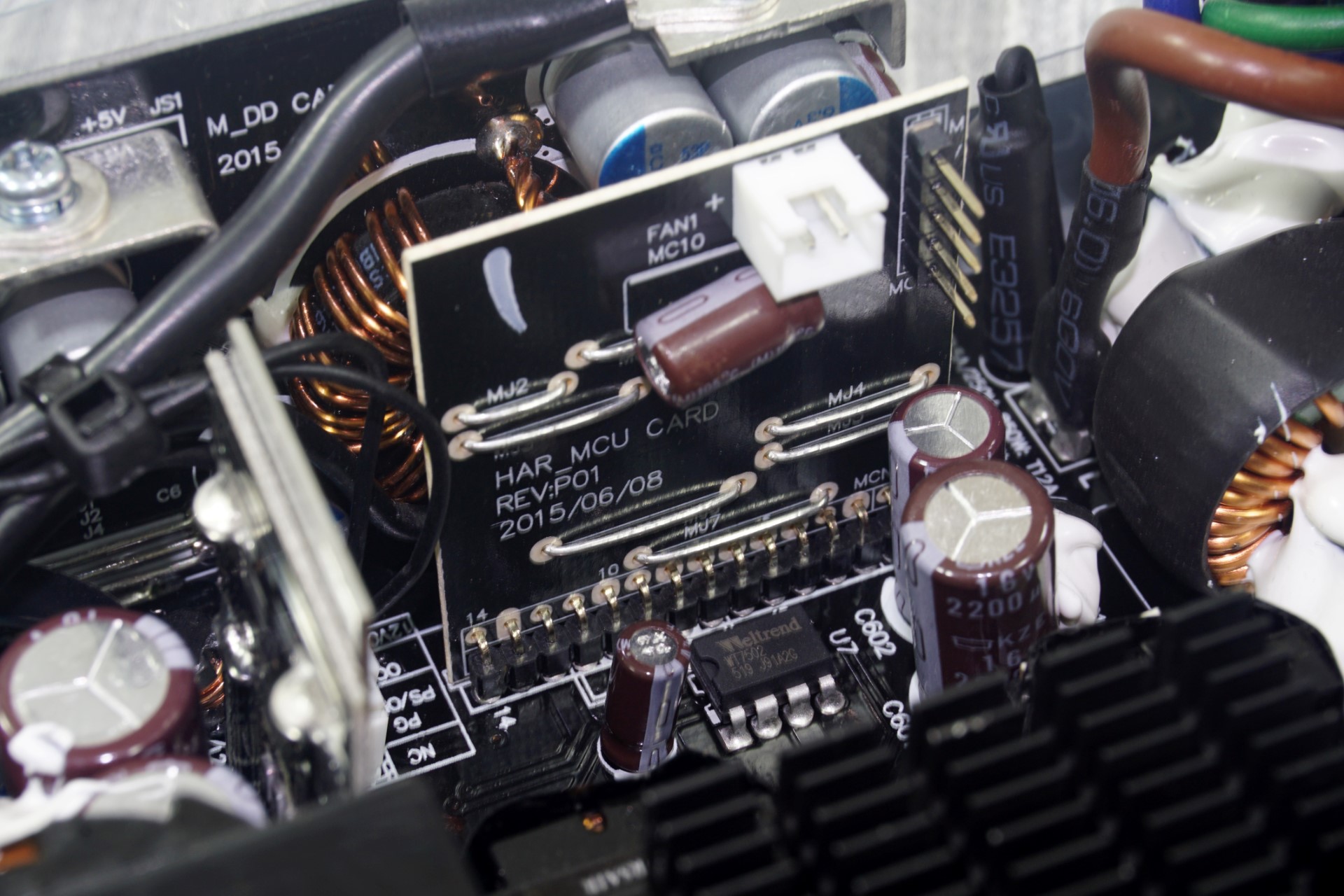
This vertical PCB is the only part that is notably different between the two units. Where the RM1000i has a microcontroller, the RM1000x is plain and shorted to follow only a core, pre-programmed thermal control set of instructions. The RM1000i's stock fan profile is identical but can be adjusted via the Corsair Link interface.


47 Comments
View All Comments
elforeign - Wednesday, September 30, 2015 - link
I do remember seeing that this was accounted for in the Cablemod custom cables and they do indeed have the proper cabling design to uphold the ripple suppression seen in the stock cables.FriendlyUser - Wednesday, September 30, 2015 - link
Great review as usual. I was wondering why nobody makes PSUs with EPS 8pin outputs... Such high-wattage units would be perfect for a dual-CPU WS.jonnyGURU - Wednesday, September 30, 2015 - link
What do you mean? MOST PSUs have EPS 8-pin connectors. Typically two for dual CPU WS's.FriendlyUser - Thursday, October 1, 2015 - link
I am sorry, I read the table quickly and just saw the line EPS-8pin empty. However, I still don't get what sort of PSU I need to power, for example, an ASUS X99-E WS, which needs (I quote from the ASUS website):2 x 8-pin EATX 12 V Power connector
1 x 6-pin EATX 12 V_1 Power connector(s)
1 x 24-pin EATX Power connector(s)
1 x 8-pin ATX 12V Power connector(s)
DanNeely - Thursday, October 1, 2015 - link
Looking at the manual (as opposed to the speclist) or pictures of the board it only has 1x24, 2x8, and 1x6 pin power connectors. The two 8 pin ones are at the top of the board and presumably are 8 pin EPS connectors. The 6pin is between the CPU and 1st PCIe slot, I assume it's a PCIe power connector. The two 8 pin and 1 6 pin connectors have opposite polarities (the 8pins have the 12V on the side with the clip, the 6pin has the ground on the clip side); which fits my recollection of differences between the two types of 12V connectors but I don't recall which is which. No clue where the supposed 3rd 8pin connector came from...DanNeely - Wednesday, September 30, 2015 - link
They do, generally in 4+4 type (eg the two EPS 4+4 Pin from the feature table here). If you have both halves of the 4+4 together it's an 8pin EPS connector. If you pop the plug apart you get a 4 pin "P4" connector suitable for use with older/low power systems or as supplemental power on some enthusiast boards. (My LGA 1151 board has both an 8 pin EPS and 4 pin P4 power connector, with the latter to provide more power for overclocking - not sure why they didn't just do 2x 8pin connectors honestly, even if they didn't need it for the CPU might be enough to remove the need for an optional PCIe6 connector around the expansion card area to power 3 way GPU setups.)extide - Wednesday, September 30, 2015 - link
Probably because they couldn't ship that much current from above the cpu socket where that connector most likely was down to the pcie slots without significant voltage drop, making it ~pointless. With really high current on a PCB you want that connector as close to the point of load as possible. I mean even with 2 oz copper you are looking at a pretty fat trace, and boards these days are pretty packed ... So you are talking about possibly adding in 2 entire extra layers...FriendlyUser - Thursday, October 1, 2015 - link
You're right, I misread the EPS-8 line which was empty and did not notice the 4+4 part. Thanks for your comment.lozikosaz - Wednesday, September 30, 2015 - link
I wish that Anandtech made more reviews for PSU in the range of 500/750W.Even entusiast PCs are maxed at that power. Even with multiple GPU.
It does not make sense to use more PSUs of higher wattage than needed, because efficiency drops, and efficiency on idle or light use (like browsing Internet or using office tools), is much worse with a high wattage PSU.
Arbie - Wednesday, September 30, 2015 - link
@lozikosaz - What do you mean? By my count, at least six people are interested in this, though of course not all will buy it.