Gigabyte GA-P55M-UD2 - P55 uATX Goodness for Under $105 - Updated
by Gary Key on August 28, 2009 12:00 PM EST- Posted in
- Gary's First Looks
We will finish up our P55 previews this weekend (or later) with a couple of new boards from ASUS and Biostar. In the meantime, I just wanted to comment on the Gigabyte GA-P55M-UD2. I have over a dozen P55 boards in the labs with several more arriving shortly. Already, two motherboards have risen to the top in regards to overclocking performance and a couple of boards have really impressed me with their balance of great performance and excellent feature sets.
That said, this particular board has been the most fun so far in testing. However, I will confess that I am partial to solid performing, budget priced, uATX form factor boards so my comments on these products tend to have some rah-rah in them if they perform well. Speaking of performance, I cannot comment on the numbers due to the NDA. Even though we have half a dozen retail purchased processors, memory kits, coolers, and this motherboard, Intel is sticking to their guns about violating the NDA release on i5/P55.
So that leaves me with providing vague comments like the board having a very good performance to price ratio. Maybe something along the lines of "I just cannot believe it does not cost more" is appropriate considering the feature set and performance compared to a few other boards.
This does not mean the board is going to hit 272 Bclks or provide class leading performance. It just means that spending less than $105 for this board and pairing it up with a Core i5-750 is going to lead to some fun times for the P55 budget seekers, HTPC groupies, or the SFF gaming crowd. We have word from ASRock and Foxconn that they will be providing $100 uATX P55 boards but we have not seen the feature sets yet.
Let's take a quick look at the GA-P55M-UD2. I forgot to mention, you can purchase this board now (as we did) from Provantage for less than $105. Update - The board is sold out again but should be in back in stock shortly, probably at less than $100.
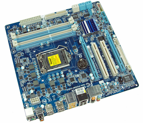
Considering the limited board space, Gigabyte did a very good job fitting all of the peripherals onto this board. About the only negatives we can think of is the continued inclusion of the floppy drive port and the lack of passive cooling for the MOSFET area. The board only sports two fan headers so that might also be a problem for users with two or more 3-pin case fans. The board does support CrossFireX operation although we highly recommend against this setup as the second PCIe x16 slot is actually an x4 electrical slot running off the P55 chipset. The board contains Gigabyte's UltraDurable 3 technology that features their 2oz. copper based PCB, solid capacitors, low RDS(on) MOSFETs, and ferrite core chokes.
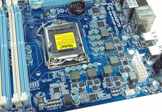
Gigabyte utilizes a solid six-phase PWM setup on this board. The CPU area is open for the most part and will accommodate larger coolers like the Thermalright MUX 120. Large push/pull coolers like the Vigor Monsoon III LT will block the first DIMM slot. If you plan on running this board with Bclk rates above 170 or so, we suggest additional airflow across the MOSFETs to ensure 24/7 stability when overclocking.
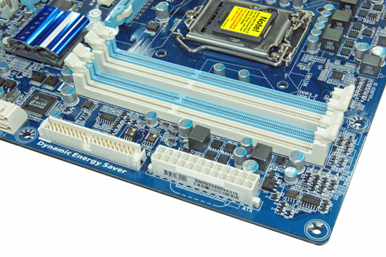
The IDE port, 24-pin ATX power connector, and the four DIMM slots are located in the lower right hand corner of the board. This board supports dual channel memory configurations and 16GB of DDR3 memory when using 4GB DIMMS. Installing the memory with a video card inserted in the first slot is difficult but not impossible.
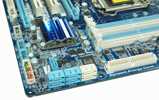
There are five (blue) SATA 3Gb/s ports provided by the P55 chipset that support RAID 0, 1, 5, 10. The sixth port available on the P55 (under the blue heatsink) is utilized on the I/O panel for eSATA. Gigabyte includes the JMicron JMB363 3Gb/s SATA chip that drives the two white SATA ports and provides IDE support. The front panel header, two USB headers, and the IEEE 1394a header are located at the edge of the board.
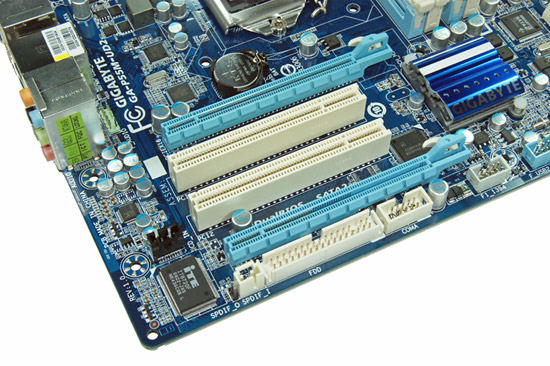
Gigabyte includes two PCIe x16 slots (x16 operation for the first slot, x4 operation for the second slot) and two PCI slots. The first PCI slot will be unavailable when utilizing a dual slot video card.
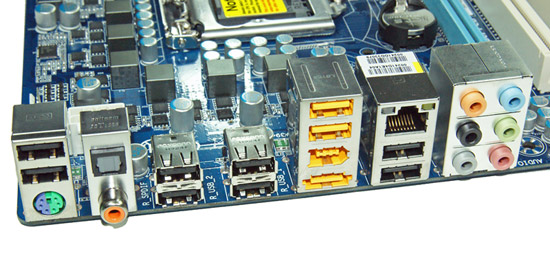
Last but not least is the I/O panel. We have ten USB 2.0 ports (total of fourteen on the board), combination PS/2 port, single eSATA port, IEEE 1394a port offered by the TI TSB43AB23 chipset, Gigabit Ethernet LAN port via the Realtek RTL8111D chipset, optical out/coaxial out S/PDIF ports, and the audio panel that provides 8-channel audio output via the Realtek ALC 888B HD audio codec.


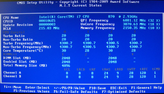
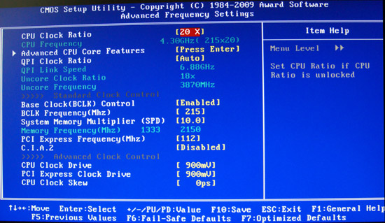
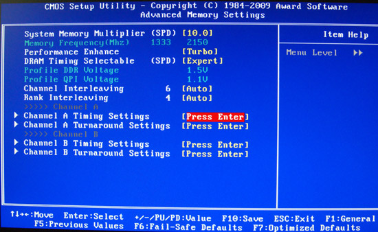
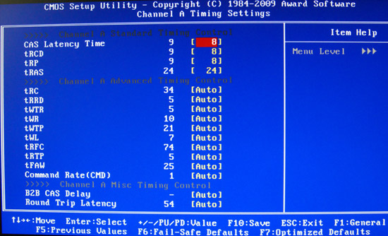
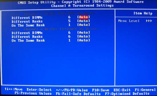
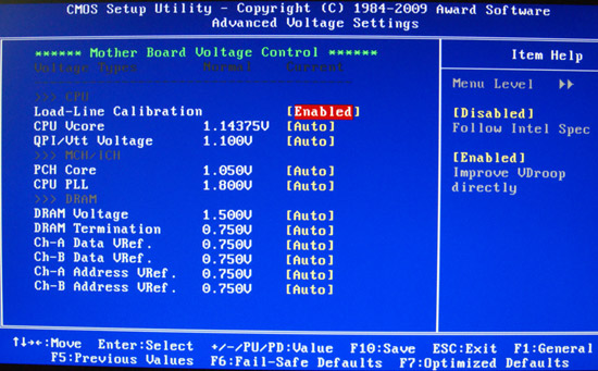
BIOS Information
Apparently this preview did not have enough substance in it according to a few reader comments. I totally agree. However, I will state this one more time, we are bound by an NDA and cannot provide that substance for another week or so. That said, we can now show the general layout of the BIOS, thus providing a little more substance than we had yesterday. I will leave it at that for now.


76 Comments
View All Comments
yacoub - Friday, August 28, 2009 - link
Now if they (or MSi or Asus) can come out with one without the floppy/IDE connector, firewire, or 8-channel mini jacks, and maybe throw in another fan header and cooling for the MOSFETs, we'd have the perfect uATX board!I can't believe they'd leave the MOSFETs naked, especially if the board allows overclocking. That seems like such a basic thing to overlook??
Otherwise very tempting! I'd pay $120 for a version with an effective MOSFET heatsink and no floppy connector. =P
Gary Key - Monday, August 31, 2009 - link
Actually, in a decent case, the lack of a passive MOSFET cooling setup is not really hurting this board in regards to clocking abilities. The temperatures are still in check, but I will be using it in a case with only the power supply providing any exhaust shortly. On a 24/7 overclocking basis, talking 20x215 settings, I would make sure the case has airflow across the board if you are not using a radial cooler on the CPU.Jeffk464 - Saturday, August 29, 2009 - link
Hey not so fast buddy. Nobody has a floppy anymore but there still a lot of dvd writers and hard drives out there floating around with IDE connectors.Taft12 - Monday, August 31, 2009 - link
I've got a boatload of IDE hard drives and optical drives, and I used to be a staunch defender of these ports remaining on motherboards, but time has broken me down, and sadly, now the correct opinion is "from now on, we should be using a PCI card for that"http://www.newegg.ca/Product/Product.aspx?Item=N82...">http://www.newegg.ca/Product/Product.aspx?Item=N82...
See you here soon :(
Etern205 - Tuesday, September 1, 2009 - link
Nowadays PCI is getting replaced with PCIe. And the Asus P6T7 WS SuperComputer is the epicenter of PCIe ridiculousness.http://www.newegg.com/Product/Product.aspx?Item=N8...">http://www.newegg.com/Product/Product.aspx?Item=N8...
Jeffk464 - Saturday, August 29, 2009 - link
Hey not so fast buddy. Nobody has a floppy anymore but there still a lot of dvd writers and hard drives out there floating around with IDE connectors.Etern205 - Tuesday, September 1, 2009 - link
I've got 2 Asus boards all of a sudden one day just will not pass POST.All it does is show up some weird error message, cannot get into bios,clear CMOS won't work, and all it does is look for the A:\. A quick look online to see what the error was and it says a corrupted bios. As to how it got corrupted I have no idea. So I've went to the Asus site, found the models I was looking for and download the bios to a floppy disk. Pop in the floppy disk to the defected board and flashed it. A few minutes the board was back up and running.
Yes in these days we don't need a floppy, but if your board all of a sudden had a corrupted bios, how are you suppose to revive it back? Does USB boot or USB emulate as floppy a default bios feature or you'll need to change it?
If it's option 2 (you well need to change the setting yourself in the bios), then you're probably SOL.
If mobo makers decides to remove the floppy connector, at least make the bios default setting with USB boot!
yyrkoon - Wednesday, September 9, 2009 - link
Using a floppy to put the BIOS back into the flash is not necessary. You can use a USB port, IDE, SATA, or even Ethernet to boot from, or flash the BIOS. There are even other methods which now days are limited to embedded devices, but if PC motherboards had the capabilities, these could be possibly used as well. Also, in your case if you had an appropriate ROM "burner" with a correct socket for the BIOS chip, you could have used that as well. I have personally done the latter here when I flashed an older system with a "hacked" BIOS using a buddies ROM burner. This was not because it failed however, it was just a means to backup the original OEM BIOS, before flashing an unknown.Anyways, my point is that "we" can use anything the OEM allows us to use, and in your case, you were limited to a floppy, or using equipment most people do not have. Another third option was also available to you ( possibly ) which was buying a working new BIOS chip from the OEM. However that is rarely ( if ever ) inexpensive by comparison.
The only reasons I can think of why they do not do this is that it may be possible that USB, or other methods of booting is more expensive to implement. Cost in currency, code ( meaning the need for a larger BIOS ), or even both. Or *maybe* they have investments in a floppy drive company or two, and are looking for continued profits? . . .
anandreader - Friday, August 28, 2009 - link
Just a guess but perhaps the 2 oz of copper is enough to keep the mosfets cool? Once the reviews are out, we'll find out if the mosfets overheat or not.Hopefully, we'll also hear which motherboards protect their Bios from rootkit attacks as well but I'm beginning to lose hope on that one.
Stele - Sunday, August 30, 2009 - link
The amount of copper on the PCB layers is really only one factor in keeping MOSFETs cool. If a manufacturer cuts corners and use 20A-rated MOSFETs in a 200A design, even a 10 oz. copper layer would be hard-pressed to keep the MOSFETs from frying at full load.Ultimately it's not about the PCB, or the MOSFET, or the PWM, or the chokes, or the capacitors separately; the whole circuit design is a system where the whole is more than the sum of its parts. Except focusing on each of those components affords 5x the marketing material as compared to one "well-designed circuit".