Gigabyte GA-EP45-UD3P - P45 at its Finest
by Gary Key on February 3, 2009 12:15 AM EST- Posted in
- Motherboards
Board Layout
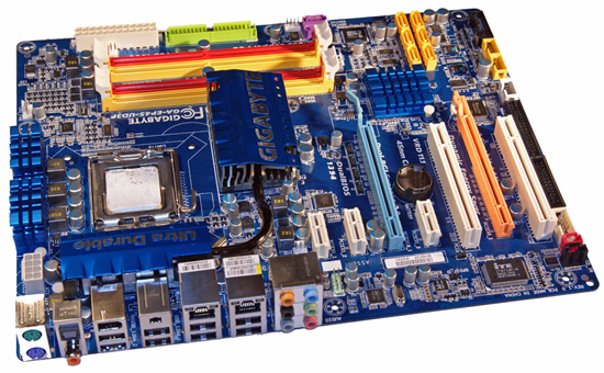
Taking a quick tour around this board, we find the overall layout is excellent. The 24-pin and 8-pin ATX power connectors, floppy/IDE connectors, and several of the SATA ports are all placed along the edge of the motherboard. We would have preferred that the SATA connectors were in a 90 degree angle configuration, but they work as is. One nice feature is that there is a double slot gap between the two physical PCI-E x16 slots so that aftermarket cooling will work. Installation of our peripherals was easy and the board fit well in several case designs. The back of the board is clean and all of our various air coolers that required a back plate worked fine. Let’s take a quick look at the rest of the board.
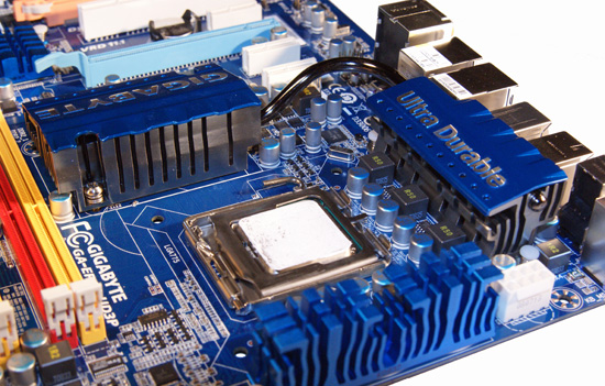
The CPU socket area is open and unobstructed for the most part. The socket area is surrounded by the Northbridge heatsink, MOSFET coolers, and several capacitors, but we had no issue installing large air coolers or a couple of water blocks. This board features a six-phase power design with three Low RDS(on) MOSFETs per channel along with the R50 ferrite core closed chokes.
Forget the marketing info about eight to sixteen phase power delivery systems; it is all about the quality of the components utilized. This board supports 30A per phase and delivers a total of 180A to the CPU. This is more than enough for any Core 2 processor in Intel’s lineup, even with heavy overclocking.
The chipset and MOSFET cooling system is well designed and works. Gigabyte connects the aluminum Northbridge heatsink to the primary MOSFET heatsink with a revised heatpipe design. The second MOSFET heatsink located on the edge of the board reminds us of Intel’s BadAxe designs. To answer the question of whether any of this works: yes, it works very well even with the system overclocked.
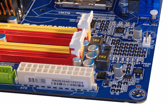
The top picture shows the phase LED setup that displays the number of power phases in use, but only when the Dynamic Energy Saver software is running. Located below the LED panel is the two-phase power system for the memory slot along with the CPU fan header that is slightly out of the way for us.
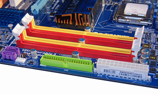
The second image shows the eye popping red and yellow memory slots. Fortunately for most of us, Gigabyte has changed to a muted color scheme on the X58 boards, but the Crayola color scheme lives on in this board. The floppy drive connector, 24-pin ATX power connector, and the two GSATA ports are located along the edge of the board.
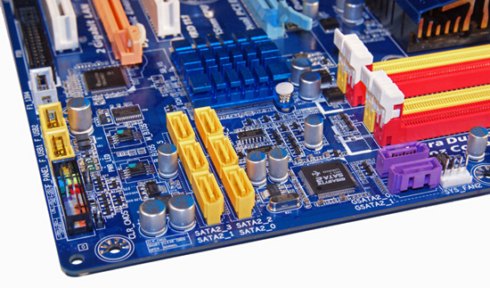
Hey, the two purple GSATA ports show up again. This rebranded JMicron controller is capable of RAID 0 and RAID 1 operation. Intel’s ICH10R provides support for the six yellow SATA ports and features RAID 0/1/5/10 capabilities with Intel’s excellent Matrix technology. The ICH10R is cooled by a low-rise aluminum heatsink . Along the left edge of the board is the black front panel connector, two yellow USB 2.0 headers, and the gray IEEE 1394a header.
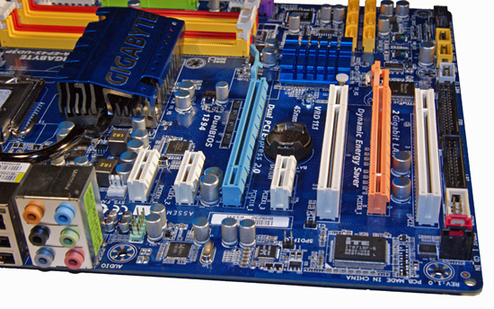
The expansion slot layout is very good and indicates that Gigabyte has been listening to users. The third PCIe x1 slot and second PCI slot become physically unusable if dual-slot graphics cards are placed in the PCIe x16 slots. Even so, with a CrossFire setup you end up with two PCIe x1 and one PCI slot open. You cannot ask for much more than that.
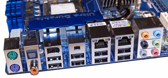
Last but certainly not least is the I/O panel. There are the standard issue PS/2 keyboard and mouse ports, two Gigabit LAN ports with LED activity lights, eight USB 2.0 ports, two IEEE 1394a ports, optical and coaxial S/PDIF ports, and an audio panel.


73 Comments
View All Comments
Archeon - Tuesday, February 3, 2009 - link
I've used this board in my main rig now for about two months. I found this board has ONE major downside, which is not mentioned in this review I think.The problem is this: there is one electronics component VERY close to one of the holes which is used to hold to cooler onto the board. You can see the component I mean when you look at the second pic on page 4 (board layout) of this review. It's the hole surrounded by all the caps. If you look closely, you'll see that right above this hole, there's some sort of flat, slightly elevated electronics component.
Why is this a problem? Because this hole is preventing me from mounting about any other cooler than the stock Intel cooler! I've tried both a Scythe Infinity (Mugen) and Ninja. I simply cannot install these coolers without pushing off the electronics component, which surely would not be a good idea. Even the stock Intel cooler of my old E6600 CPU doens't fit!! (Luckily the stock cooler of my E8500 does!)
So now I run my rig with the stock Intel cooler, which is a shame since I have such a nice Mugen cooler readily available here, but it just won't fit!!! This is bad board design INHO, nothing less, nothing more.
Apart from this issue, I absolutely love this board: rock solid, and all the features I need (and then some!)
The0ne - Tuesday, February 10, 2009 - link
Looks like an oscillator to me and it does appear to sit too close to the locking hole. However, the photo might be deceiving my eyes. But judging from the pics alone I'm pretty sure my Artic Freezer 7 fan wouldn't fit on there. The clips will hit the component as well. However, my fan does sit fine in my EP45-DS3R but it's a bit different board.7Enigma - Tuesday, February 3, 2009 - link
Hmm, that is odd as the reviews seemed to say that most of the common high-end coolers had no problem. I have the Xigmatech 120mm Rifle cooler and it installed with no clearance issues (pushpin pieces of $hit are another story). Is it that you want to mount the cooler in a specific orientation and it won't work, or that there is no way that any direction would work?Archeon - Wednesday, February 4, 2009 - link
No specific orientation. It didn't work in either way. I even bought [url=http://www.scythe-eu.com/en/products/pc-accessory/...">http://www.scythe-eu.com/en/products/pc-accessory/...]Scythes CPU Cooler stabiliser[/url] in the hope that would work, but again, no go...LoneWolf15 - Tuesday, February 3, 2009 - link
and I have to say, this board is the best I've ever owned. Tons of features and ports, (including two PS/2 ports for you KVM users, yes, I'm talking to you ASUS) a great layout, loads of BIOS options, rock-solid stability --about the only things I could nitpick about are Gigabyte's funky color scheme, and perhaps not having right-angle front-mounted SATA ports. Both very minor details. It's working well with two 4GB DDR2 modules and a Q6600.I'd recommend this board to anybody, it's a quality part. Thanks for the review, AT.
7Enigma - Tuesday, February 3, 2009 - link
I just built a rig using the R (single GPU) mobo and have had some problems upgrading my rig from an old 80gig PATA drive to a new 320gig SATA drive. Here is my problem:-I installed Vista 64bit on the new rig with my old 80gig drive and then decided I wanted to rebuild my old rig (replaced everything but case and HD) using the old drive. I need to clone my 80gig onto my 320gig so I can swap the old drive out. Problem is when I connect the SATA drive using the 90 degree elbow SATA cable that says HD, it is not recognized in windows. I can find it in the device manager, and it says it is working properly, but there is no way to copy/format/etc. to it?
I've tried using both the 6 orange SATA ports, and also the 2 purple ports (I don't know if there is a difference here or not), but no luck. Should I try a no 90degree elbow cable? I'm unfamiliar with SATA tech and so wonder if the 90degree cable designates the SATA drive as master, and I need to have it as a slave? When I go into the bios BOTH drives come up as MASTER, but seem to be on different channels so I didn't think this was an issue.
Sorry to take this off topic but I spent a couple hours this past weekend and got nowhere.
I have another issue that seems to be related to some power saving thing with this board. Before I turned off the power saving features in the bios it would seem to randomly not like to start from a cold boot (I'd have to turn it off and on, or restart if it got to the bios screen). It almost seemed like it was cutting power too quickly on shutdown and startup. Most of the issues seem to have gone away since I turned off the power saving functions, but I still get some squirly things happening when turning on for the first time. I'm currently using optimized defaults in the bios so it's not a wierd overclocking issue.
Thanks for the advice.
7Enigma - Tuesday, February 3, 2009 - link
Wanted to mention this is with the latest chipset drivers and the F7 bios. I LOVE the online bios update. No more floppy flashes for me!Mr Roboto - Sunday, February 15, 2009 - link
Yeah, that's an old Gigabyte feature. When I used it on my old AMD based GA-K8U-939 it worked flawlessly then. People rip on Gigabyte's BIOS support and complain about bad flashes but I've NEVER had any of those problems with them.However on less popular boards BIOS support is slow.
Glenn - Tuesday, February 3, 2009 - link
I suggest you review the owners manual and make sure which SATA controller you are connected to and ensure that it is properly set in the bios for your configuration. I suspect you have whichever controller you are connected to, to AHCI or Raid and it isn't recognized. I know it's confusing until you get used to it, but SATA doesn't use the old master slave ...!7Enigma - Tuesday, February 3, 2009 - link
Wanted to also add I tried both the G-SATA (purple connectors) and the standard orange Intel ones with no effect. It wasn't until I quit and removed the SATA drive that I thought to try the non 90 degree elbow one that says HDD on the cable. Can you comment on whether there are specific SATA cables that denote HD's or whether they just had the 90 degree bend to facilitate placement in the case without stressing the connectors (I have read many complaints on breaking off).