Gigabyte GA-EP45-UD3P - P45 at its Finest
by Gary Key on February 3, 2009 12:15 AM EST- Posted in
- Motherboards
Board Layout
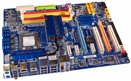
Taking a quick tour around this board, we find the overall layout is excellent. The 24-pin and 8-pin ATX power connectors, floppy/IDE connectors, and several of the SATA ports are all placed along the edge of the motherboard. We would have preferred that the SATA connectors were in a 90 degree angle configuration, but they work as is. One nice feature is that there is a double slot gap between the two physical PCI-E x16 slots so that aftermarket cooling will work. Installation of our peripherals was easy and the board fit well in several case designs. The back of the board is clean and all of our various air coolers that required a back plate worked fine. Let’s take a quick look at the rest of the board.
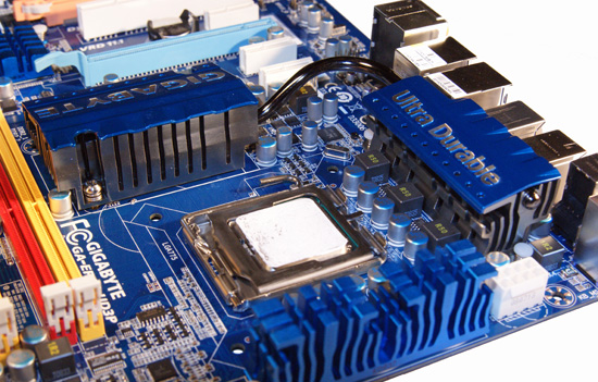
The CPU socket area is open and unobstructed for the most part. The socket area is surrounded by the Northbridge heatsink, MOSFET coolers, and several capacitors, but we had no issue installing large air coolers or a couple of water blocks. This board features a six-phase power design with three Low RDS(on) MOSFETs per channel along with the R50 ferrite core closed chokes.
Forget the marketing info about eight to sixteen phase power delivery systems; it is all about the quality of the components utilized. This board supports 30A per phase and delivers a total of 180A to the CPU. This is more than enough for any Core 2 processor in Intel’s lineup, even with heavy overclocking.
The chipset and MOSFET cooling system is well designed and works. Gigabyte connects the aluminum Northbridge heatsink to the primary MOSFET heatsink with a revised heatpipe design. The second MOSFET heatsink located on the edge of the board reminds us of Intel’s BadAxe designs. To answer the question of whether any of this works: yes, it works very well even with the system overclocked.
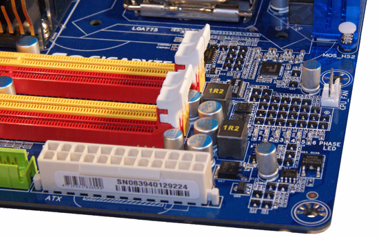
The top picture shows the phase LED setup that displays the number of power phases in use, but only when the Dynamic Energy Saver software is running. Located below the LED panel is the two-phase power system for the memory slot along with the CPU fan header that is slightly out of the way for us.
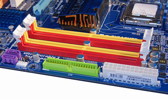
The second image shows the eye popping red and yellow memory slots. Fortunately for most of us, Gigabyte has changed to a muted color scheme on the X58 boards, but the Crayola color scheme lives on in this board. The floppy drive connector, 24-pin ATX power connector, and the two GSATA ports are located along the edge of the board.
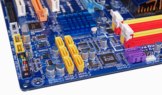
Hey, the two purple GSATA ports show up again. This rebranded JMicron controller is capable of RAID 0 and RAID 1 operation. Intel’s ICH10R provides support for the six yellow SATA ports and features RAID 0/1/5/10 capabilities with Intel’s excellent Matrix technology. The ICH10R is cooled by a low-rise aluminum heatsink . Along the left edge of the board is the black front panel connector, two yellow USB 2.0 headers, and the gray IEEE 1394a header.
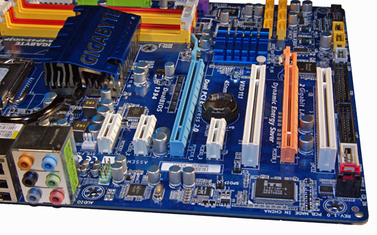
The expansion slot layout is very good and indicates that Gigabyte has been listening to users. The third PCIe x1 slot and second PCI slot become physically unusable if dual-slot graphics cards are placed in the PCIe x16 slots. Even so, with a CrossFire setup you end up with two PCIe x1 and one PCI slot open. You cannot ask for much more than that.
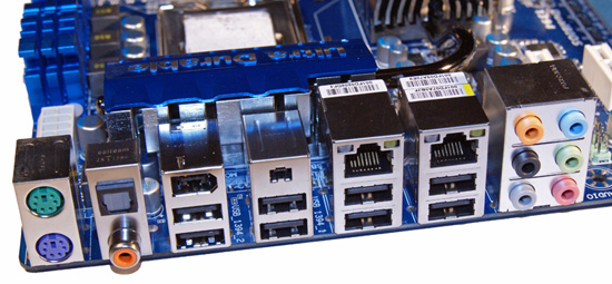
Last but certainly not least is the I/O panel. There are the standard issue PS/2 keyboard and mouse ports, two Gigabit LAN ports with LED activity lights, eight USB 2.0 ports, two IEEE 1394a ports, optical and coaxial S/PDIF ports, and an audio panel.


73 Comments
View All Comments
NimitzHarrington - Monday, February 9, 2009 - link
Hi Gary,Excellent review. I'm glad I chose this board when I built my new system a couple of months back.
However, I have not managed to get eSata fully working on this board. When I plug in an eSata HDD, Vista picks it up but it's listed as an internal disk. Therefore, I cannot remove it from "Safely remove hardware".
I tried the latest Intel Storage Manager, but that did not help. I have had to resort to using HotSwap.
Have you come across this during your testing (or has anyone else using this MB experienced and fixed this issue)?
Thanks.
Lazlo Panaflex - Thursday, February 5, 2009 - link
An 8600 @ 5Ghz+...very nice o/c! I reckon that setup would fetch a pretty penny on Fleabay (unless Gary's using it as his main gaming rig...hehe ;)vlado08 - Wednesday, February 4, 2009 - link
I expected core i7 architecture to use less power than core2 Quad in "idle" mode because it can switch off unused cores. So if I have a computer which is 24/7 in "on" state then the best power efficiency will be to use core 2 Duo. For example if it is used for downloading/uploading from internet.It seems I was wrong. Or may be it is a Vista problem failing to switch off unused cores of core i7?
jzodda - Wednesday, February 4, 2009 - link
Have had it since october running my E8400@ 4.2ghz and 525 FSB 24/7This board is really a pleasure to work with once you get the hang of the various bios settings. Took awhile back then. Now there is an 1800 post thread at X-treme so info is no longer lacking on any setting.
This board is a throw back to the good old Abit days of the BH6 and boards like it. Lots of fun.
SixOfSeven - Tuesday, February 3, 2009 - link
LoneWolf15, what 4GB DDR2's are you using? Any problems setting things up?LoneWolf15 - Thursday, February 5, 2009 - link
"LoneWolf15, what 4GB DDR2's are you using? Any problems setting things up? "I apologize here. I used two 2GB modules, not two 4GB ones, and couldn't go back and re-edit.
I'm using G.Skill Pi DDR2-800 modules which work at 1.8-1.9v with 4-4-4-12 timing. They're available at the `Egg for $45-50 a set with free shipping, and they're hassle free. Almost tempting to get a second set for Windows 7 x64 when it comes out.
7Enigma - Wednesday, February 4, 2009 - link
Just wanted to add (even though you didn't ask) I'm using the 2X2gig Reaper ram that has the heatpipe with a huge heatsink on top (making the ram 2-3" taller than it would normally be). There are no clearance issues at all.Matt Campbell - Tuesday, February 3, 2009 - link
Time to break out the LN2 and see how far it really goes ;)Freak Out - Tuesday, February 3, 2009 - link
I was wondering if you could post a picture of the test setup?Gary Key - Wednesday, February 4, 2009 - link
Let me get one before I tear it down today.