A Lesson in User Failure: Investigating the Serial ATA Connector
by Ryan Smith on January 18, 2008 12:00 AM EST- Posted in
- Storage
SATA Anatomy, Failure Anatomy
It’s best to start first with a quick history lesson on the SATA design, as it hasn’t been static through the years. It has gone through some important revisions - some visible and some not – that have shaped the SATA connector in to what we see today. We’d also like to thank Knut Grimsrud, chairman of the SATA International Organization and Intel Fellow in their Technology & Manufacturing group for helping us out with this article and answering some of our questions.
First and foremost, the SATA-IO identified issues early on with the design of the SATA connector, and has revised it several times. This is most obvious in the move from the SATA 1 motherboard connector to the SATA 2 motherboard connector, where the SATA 1 motherboard connector was far more exposed than the SATA 2 connector. This switchover was particularly evident on boards using both native and external SATA controllers, where one would be SATA 2 compliant and the other SATA 1, requiring the different connectors.
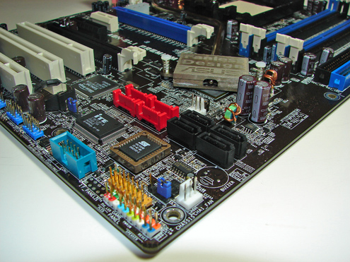
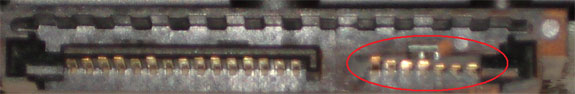
The SATA 2 motherboard connector added shrouding around the connector, which significantly improved the durability of the connector as the shrouding prevented cables from easily bending the wafer part of the connector. Unfortunately this kind of shrouding couldn’t be added to SATA devices, because the standard was designed for use in small devices that don’t have clearance to fit a full shroud. This results in the modern half-shroud design for devices, where the top-half of the connector is shrouded by the device but not the bottom half.
The other significant changes in the standard since its inception have been latching and chamfering. Most SATA devices now have recesses in their top side shroud that allow barbs on SATA cables to latch in to in order to provide downward stability since the underside is the unshrouded side. Chamfering has been added to the square edges of the tongue, and while not a visibly dramatic change, we’ve been told this is one of the primary improvements in strengthening the SATA connector.
Yet in spite of these changes we’ve still managed to do something wrong and break the connector on our hard drive. For the reason why, we’ll start with case designs and cable designs.
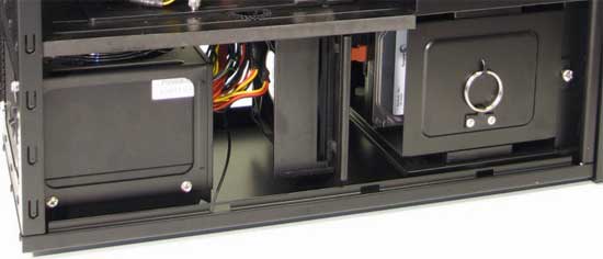
Part of our problem can be attributed to the amount of space we have to work in with the case involved in this investigation, the Antec P182. The P182, like many other cases, doesn’t leave a lot of space behind the primary hard drive bay. For most cases this is because there are motherboard components and cards in the way, while with the P182 it’s a matter of a 120mm fan being located behind the hard drive bay, which helps pull air through the lower chamber. Either way, with this specific case, we measure that we have about 2” between the rear end of a hard drive and the fan, which is very little space to work in.
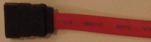
We then come to the cable, in this case it was a bog-standard cable that came with one of the products we’ve used over the years. As we mentioned earlier, SATA cables aren’t quite as flexible as PATA cables when it comes to longitudinal bending, and while we can technically bend a cable completely over at any location, this isn’t great because it causes the cable to pull back in to a more relaxed position. From the tip of the connector, the cable we measured needs about 2.5” of space to bend comfortably.
With the amount of clearance we have being less than the amount of space to need to ideally bend the cable, it becomes obvious that this will quickly become tricky. We need to bend the cable at a sharper angle so that it stays well clear of the fan, which means it’s going to be exerting some force on our hard drive, a generally acceptable but not ideal situation.
And then finally there is the layout of the P182’s hard drive bay. The P182 requires the hard drives to be installed in to the cage at an angle, such that they are on their sides with the bottom pointing towards the bottom of the case, which you can see here. Keep in mind the fact that the top hard drive is on the opposite side of the case from where the motherboard is.
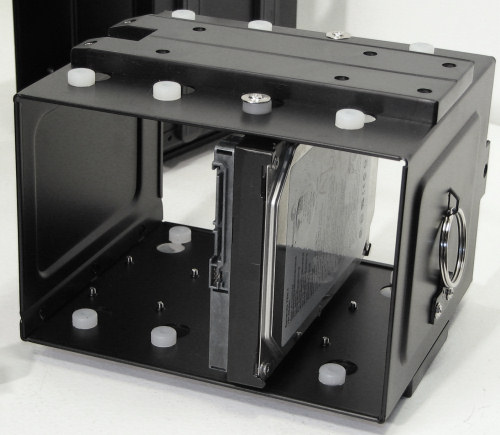
In this combination, we have the anatomy of our failure. Our cable is putting force on the SATA data connector towards the bottom side, which as we covered earlier is the weaker direction to go because it’s not shrouded like the top side is. Furthermore we’re using a SATA-1 style cable without a latch, which means we don’t have said latch to reinforce the connection. It turns out that this is enough force to break the SATA data connector on our hard drive, and when the drive cage was being secured one day the connector broke.


62 Comments
View All Comments
jay401 - Friday, January 18, 2008 - link
oh, beaten by about an hour, lol oops.elpresidente2075 - Friday, January 18, 2008 - link
It would be neat if they used a connector like the breakout box for VGA/DVI on the Macbooks. They have basically a little nub, approx 1/4 inches thick and 1/2 inch wide with about 1/4 inch of depth, with the contacts on either side. The cable is a male connector with the female on the unit. Quite possibly the most robust way of doing things I can think of at this scale.Cr0nJ0b - Friday, January 18, 2008 - link
This first time I couldn't get the drive to be seen again by the OS, so I was out of luck...the second time, I had enough of a connection with my quick patch, to allow me to recover the data. I have to agree that it's all my fault that it happened, but in these modern times, did no one on the SATA committee see that this would be an issue? It's a really flimsy connectory...with no housing...It takes almost no force to break on off and the connectors stick out so darn far that the torque from their own weight plus the cable is a continual strain on the connector. This is something that should have been fixed IMO.Ryan Smith - Friday, January 18, 2008 - link
To be fair, they already have done a bunch of work to fix the problem. Talking to Knut, we get the impression that the problem is very uncommon these days.The funny thing is that it seems to vary a lot depending on the manufacturer. For the photos in this this article I broke an old Maxtor hard drive rather than pull apart the repaired drive for photos. The Maxtor refused to break, in spite of bending it far harder than I ever did with the original broken drive it still took some time to wear it down. I can't imagine why, but it seems like some of this is just a roll of the dice, with the plastics used in the connectors not always holding up to the same conditions.
RaulF - Friday, January 18, 2008 - link
Same for me, im going to glue them today hopefully i'll get a conection.alfredska - Friday, January 18, 2008 - link
I'm sorry that I don't share in everyone else's enthusiasm, but this is probably the most pointless article I've read on AnandTech to date.JohnnyCNote - Friday, January 18, 2008 - link
Then why did you read it, and then take MORE time to post a comment? I come across articles all the time that I don't find interesting. I've found that by ignoring them, I can save a lot of time. You may find it will work for you, too . . .KikassAssassin - Friday, January 18, 2008 - link
This is an issue I hadn't really thought about before when building my PCs, and now it's something I'm going to be watching out for more in the future (and I'm going to be checking my SATA connectors when I get home to make sure they're not being strained), so if reading this article prevents me or others from breaking a hard drive at some point, then it was hardly pointless.There's more to building PCs than looking at benchmarks, so I appreciate articles like this try to make the PC builder's life a little bit easier.
jasonnovak - Friday, January 18, 2008 - link
I've done the same thing before while trying to reposition a drive in a case... I didn't think I ever put too much stress on the connector, but it snapped off the same way, with the pins still on the drive and the PCB stuck in the cable end. I was able to carefully slip the cable end/pcb back over the pins, though I should probably glue the cable to the drive so the pins don't snap off at some point.ModelTech - Friday, January 18, 2008 - link
I'd just like to say thanks for this article. I'm building a new system right now with a 182 case. When I order the drives I now know to order the SATA2 cables with a 90deg bend with them too. You probably saved me a lot of frustration. Keep it up.