Intel P965: The Double Mint Twins Gone Wild
by Gary Key on November 9, 2006 8:00 PM EST- Posted in
- Motherboards
Gigabyte GA-965P-S3: Board Layout and Features
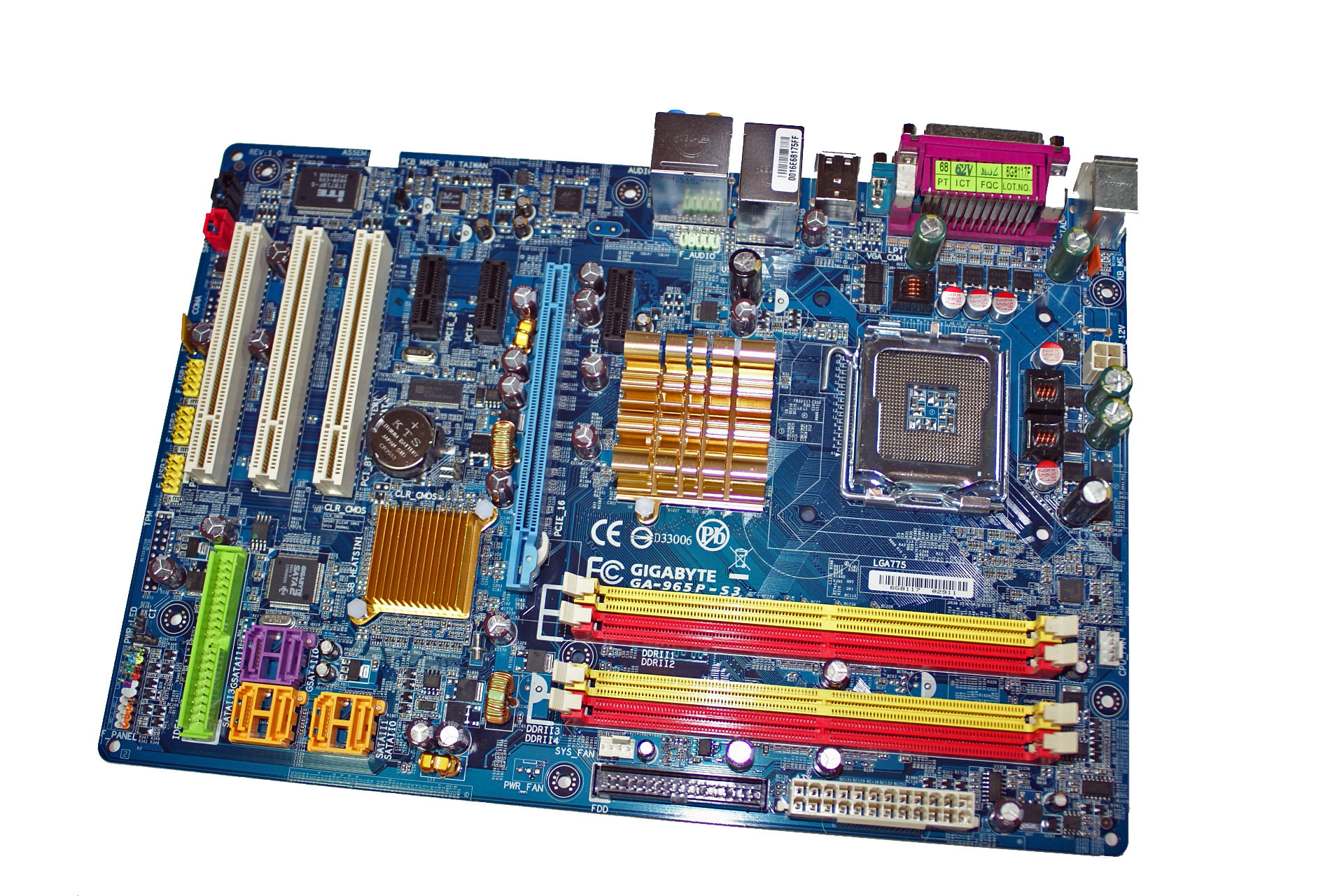
Gigabyte has engineered a nice board with a very good layout that unfortunately keeps the same color combination (or lack thereof) from the DS3. The board installed into our case without problems and all connections were easily reached. The board features a three-phase voltage regulator system that provided excellent stability throughout our testing. Unlike the DS series that use 100% Conductive Polymer Aluminum Solid Capacitors our S3 board uses a combination of solid and electrolytic capacitors. The purpose of the Conductive Polymer Aluminum Solid capacitors is theoretically to improve system durability and to provide for added stability under heavy load operations such as overclocking. However, we did not notice any differences in our testing, but the long term benefits of the solid capacitors could be significant in terms of the board's lifespan.
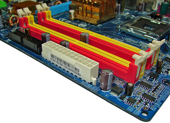
The DIMM module slots' color coordination is once again correct for dual channel setup based upon the premise of installing DIMMs in the same colored slots for dual-channel operation. The memory modules are slightly difficult to install with a full size video card placed in the PCI Express x16 slot. The 24-pin ATX power connector and black floppy drive connector are located along the edge of the board and behind the DIMM slots. The board only comes with two fan headers with the CPU fan header being located to the right of the first DIMM slot. We usually prefer a minimum of four fan headers on a motherboard.
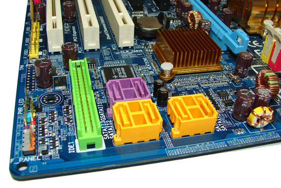
The four Intel ICH8 SATA ports are color coded yellow and the two JMicron JMB363 SATA ports are in a wonderful shade of lavender next to the green IDE connector. We found the positioning of the SATA ports to be excellent when utilizing the PCI 2.3 slots although we still prefer the IDE connector on the edge of the board to facilitate better cable management. The ICH8 is passively cooled with a gold colored low-rise heatsink and remained fairly cool to the touch throughout testing.
The chassis panel is located at the bottom left corner of the board. The clear CMOS jumper is located in between the battery and ICH8 chipset. This is a two pin configuration and requires the use of a pen to reach and is blocked if a card is installed in the first PCI slot. It seems to be a trend lately of the various manufacturers to place this jumper in the most inconvenient locations. Until the BIOS recovery programs work 100% of the time it would be nice to have this jumper out in the open, or even better go with the "button" design that we've seen used by a few manufacturers.
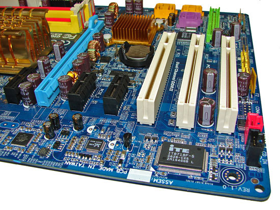
The board comes with one physical PCI Express x16 connector, three PCI Express x1 connectors, and three PCI 2.3 connectors. The layout of this design offers a very good balance of expansion slots for a mainstream performance board while providing excellent clearance space for graphics card utilization. The second PCI Express x1 slot will be blocked by a dual slot graphics card but considering the dearth of PCI Express peripherals this is fully acceptable. The first PCI Express x1 slot is a tight fit as a card installed in this slot will have minimal clearance between the MCH heatsink and video card.
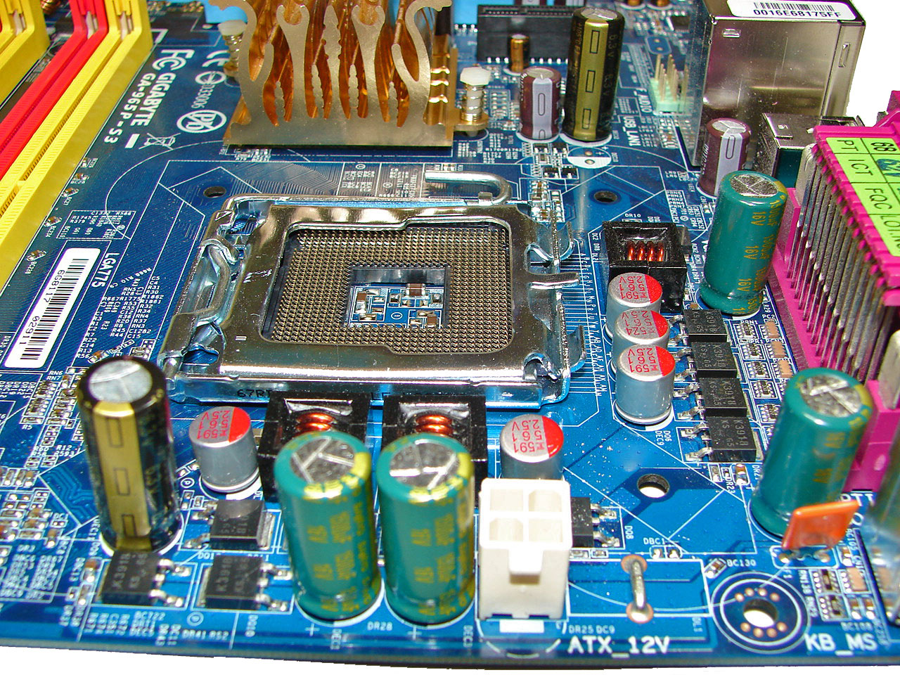
Returning to the CPU socket area, we find an ample amount of room for the majority of cooling solutions. We utilized the stock heatsink/fan in our base testing but also verified several of the larger Socket-775 cooling solutions would fit in this area during our overclocking tests. The 4-pin ATX power connector is placed on the far right side of the board and did not interfere with our various cooling units.
The Intel P965 MCH chipset is passively cooled with a mid-rise heatsink unit that did not interfere with any installed peripherals. Unfortunately, this heatsink is not very good at keeping the MCH cool during heavy overclocking. Gigabyte has used this design for the past year but has generally shipped a small fan that attaches to it for additional cooling. This heatsink needs it when running the system above 400FSB. However, even if it were included this board only has two fan headers which is not representative of a performance oriented board.
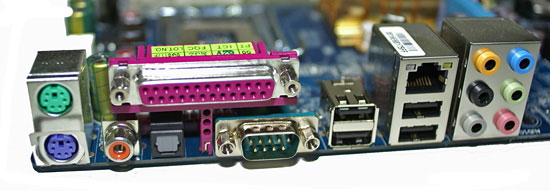
The rear panel contains the standard PS/2 mouse and keyboard ports along with serial and parallel ports for those who still require legacy peripherals. The panel also includes a LAN port, 4 USB ports, and two S/PDIF (optical out/coaxial out) ports. The LAN (RJ-45) port has two LED indicators representing Activity and Speed of the connection through the Marvell 88E8056 Gigabit PCI-E chipset. The audio panel consists of 6 ports that can be configured for 2, 4, 6, and 8-channel audio connections for the Realtek ALC 883 HD codec. The only item missing from our wish list would be a Firewire port if the board supported it.
 |
| Click to enlarge |
Gigabyte has engineered a nice board with a very good layout that unfortunately keeps the same color combination (or lack thereof) from the DS3. The board installed into our case without problems and all connections were easily reached. The board features a three-phase voltage regulator system that provided excellent stability throughout our testing. Unlike the DS series that use 100% Conductive Polymer Aluminum Solid Capacitors our S3 board uses a combination of solid and electrolytic capacitors. The purpose of the Conductive Polymer Aluminum Solid capacitors is theoretically to improve system durability and to provide for added stability under heavy load operations such as overclocking. However, we did not notice any differences in our testing, but the long term benefits of the solid capacitors could be significant in terms of the board's lifespan.
The DIMM module slots' color coordination is once again correct for dual channel setup based upon the premise of installing DIMMs in the same colored slots for dual-channel operation. The memory modules are slightly difficult to install with a full size video card placed in the PCI Express x16 slot. The 24-pin ATX power connector and black floppy drive connector are located along the edge of the board and behind the DIMM slots. The board only comes with two fan headers with the CPU fan header being located to the right of the first DIMM slot. We usually prefer a minimum of four fan headers on a motherboard.
The four Intel ICH8 SATA ports are color coded yellow and the two JMicron JMB363 SATA ports are in a wonderful shade of lavender next to the green IDE connector. We found the positioning of the SATA ports to be excellent when utilizing the PCI 2.3 slots although we still prefer the IDE connector on the edge of the board to facilitate better cable management. The ICH8 is passively cooled with a gold colored low-rise heatsink and remained fairly cool to the touch throughout testing.
The chassis panel is located at the bottom left corner of the board. The clear CMOS jumper is located in between the battery and ICH8 chipset. This is a two pin configuration and requires the use of a pen to reach and is blocked if a card is installed in the first PCI slot. It seems to be a trend lately of the various manufacturers to place this jumper in the most inconvenient locations. Until the BIOS recovery programs work 100% of the time it would be nice to have this jumper out in the open, or even better go with the "button" design that we've seen used by a few manufacturers.
The board comes with one physical PCI Express x16 connector, three PCI Express x1 connectors, and three PCI 2.3 connectors. The layout of this design offers a very good balance of expansion slots for a mainstream performance board while providing excellent clearance space for graphics card utilization. The second PCI Express x1 slot will be blocked by a dual slot graphics card but considering the dearth of PCI Express peripherals this is fully acceptable. The first PCI Express x1 slot is a tight fit as a card installed in this slot will have minimal clearance between the MCH heatsink and video card.
 |
| Click to enlarge |
Returning to the CPU socket area, we find an ample amount of room for the majority of cooling solutions. We utilized the stock heatsink/fan in our base testing but also verified several of the larger Socket-775 cooling solutions would fit in this area during our overclocking tests. The 4-pin ATX power connector is placed on the far right side of the board and did not interfere with our various cooling units.
The Intel P965 MCH chipset is passively cooled with a mid-rise heatsink unit that did not interfere with any installed peripherals. Unfortunately, this heatsink is not very good at keeping the MCH cool during heavy overclocking. Gigabyte has used this design for the past year but has generally shipped a small fan that attaches to it for additional cooling. This heatsink needs it when running the system above 400FSB. However, even if it were included this board only has two fan headers which is not representative of a performance oriented board.
The rear panel contains the standard PS/2 mouse and keyboard ports along with serial and parallel ports for those who still require legacy peripherals. The panel also includes a LAN port, 4 USB ports, and two S/PDIF (optical out/coaxial out) ports. The LAN (RJ-45) port has two LED indicators representing Activity and Speed of the connection through the Marvell 88E8056 Gigabit PCI-E chipset. The audio panel consists of 6 ports that can be configured for 2, 4, 6, and 8-channel audio connections for the Realtek ALC 883 HD codec. The only item missing from our wish list would be a Firewire port if the board supported it.


23 Comments
View All Comments
Gary Key - Thursday, November 9, 2006 - link
It is coming. We had to retest all of the high-end boards with CrossFire capability since the official 6.10 drivers we used generated measurable differences (sometimes better than 7%) in several games compared to the early beta 6.10 drivers. We did not see this issue with our single card testing.Sho - Thursday, November 9, 2006 - link
Ah, ok :). Rock on.JarredWalton - Friday, November 10, 2006 - link
Gary also neglected to tell you about his latest hard drive "testing", in the which he lost many of his in-the-work articles. I keep telling him that he shouldn't stress test his own hardware, but does he listen? Noooo! I really ought to run RAID 1 or start do more frequent backups, come to think of it....