Intel P965: Mid-Range Performance Sector Roundup
by Gary Key on October 20, 2006 9:00 PM EST- Posted in
- Motherboards
ASUS P5B-E: Board Layout and Features
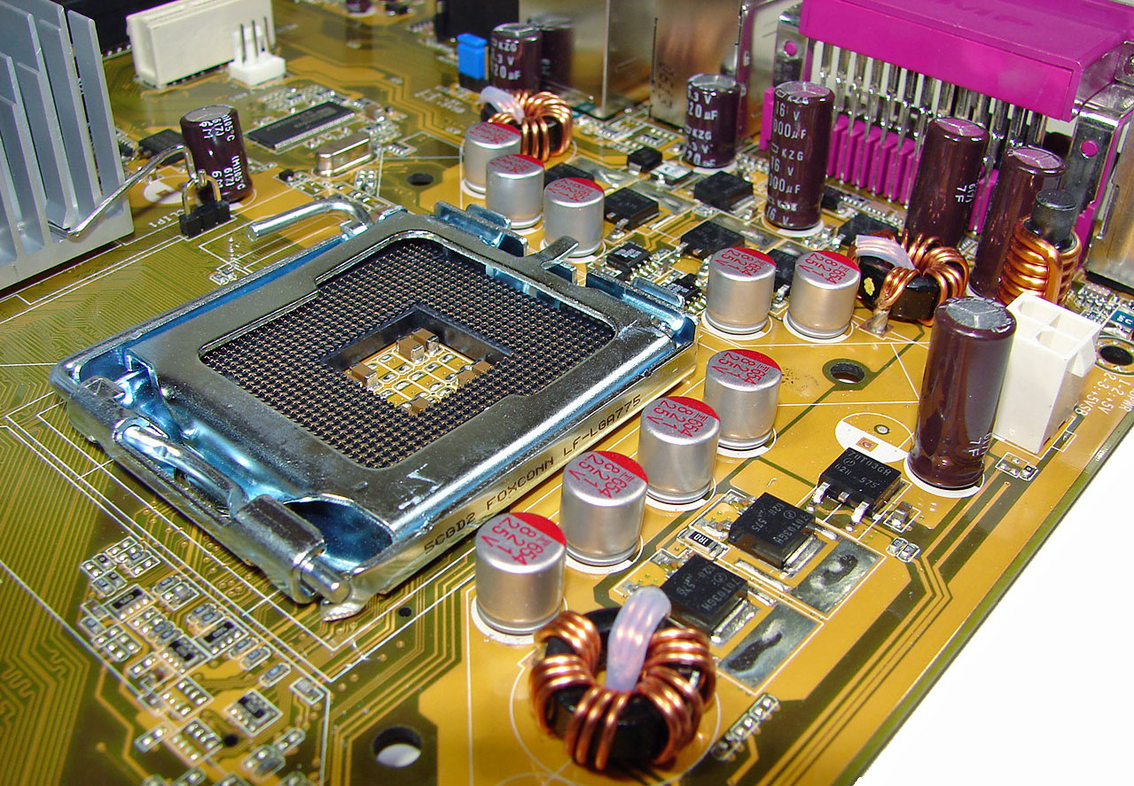
After viewing the Abit AB9-Pro, the layout on the ASUS seems almost mundane. However, we have no real complaints about the layout except for the location of the IDE port and 24-pin ATX power connector. We feel like the IDE port connector should have been placed next to the floppy drive connector or replaced it. It would have been nice to have the 24-pin ATX connector located further to the right behind the memory slots. The motherboard was very easy to install and remove from our case. The four fan headers were within easy reach and can be controlled by the Q-Fan utility. The P5B-E replaces the P5B model. We tested both the 1.01G and 1.02G revision level boards and they are identical except for the BIOS changes and a PLL controller. Both boards feature an excellent three-phase voltage regulator power design along with high quality capacitors that yielded exceptional stability.
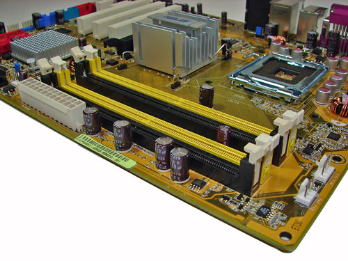
The DIMM module slots' color coordination is correct for dual channel setup based upon the premise of installing DIMMs in the same colored slots for dual-channel operation. The memory modules are slightly difficult to install with a full size video card placed in the PCI Express x16 slot. The 24-pin ATX power connector is located along the edge of the board along with a series of capacitors for the memory modules. We would have moved the 24-pin ATX connector to the upper right corner of the board to allow for easier access to the memory modules and CPU area in our case. It would also help to facilitate installation of PSUs with cables that are not longer than normal.
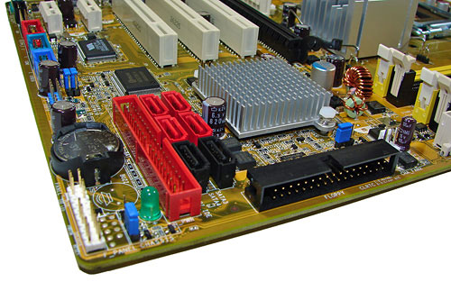
The four primary Intel ICH8R SATA ports are red along with the two secondary ports being black. These ports are conveniently located to the left of the ICH8R Southbridge and right of the battery and IDE port connector. We found the positioning of the SATA ports to be excellent when utilizing either the PCI-E x1 or PCI 2.3 slots. The ICH8R is passively cooled with a low rise heatsink and remained cool to the touch throughout testing.
The black floppy drive connector is located on the edge of the board and should have been switched with IDE port connector, as IDE cables are used far more than floppy cables these days. This switch would have eased installation of the IDE cable when using both the IDE and SATA ports. The clear CMOS jumper is color coded blue and is located in between the floppy drive connector and ICH8R chipset. This jumper was very difficult to use when utilizing a double slot video card. The chassis panel is located at the far left corner of the board.
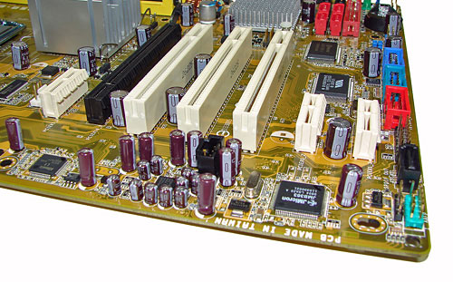
The board comes with (1) physical PCI Express x16 connector, (3) PCI Express x1 connectors, and (3) PCI 2.3 connectors. The layout of this design offers an excellent balance of expansion slots and provides very good clearance for most of the slots. When utilizing a double slot video card the first PCI slot is physically blocked and cannot be used. However, this still leaves two open PCI slots for use and all three PCI Express x1 slots. The black JMicron SATA port is on the right edge of the board along with the Firewire, COM1, and USB headers.
Returning to the CPU socket area, we find an ample amount of room for alternative cooling solutions that include most air and water cooling solutions. The Intel P965 MCH chipset is passively cooled with a mid-rise heatsink that did not interfere with any installed peripherals. This heatsinsk kept the MCH temperatures in check so that additional chipset voltage was not a factor in our overclocking tests. ASUS places the 4-pin ATX connector in the upper right section of the board and out of the way of the CPU area.
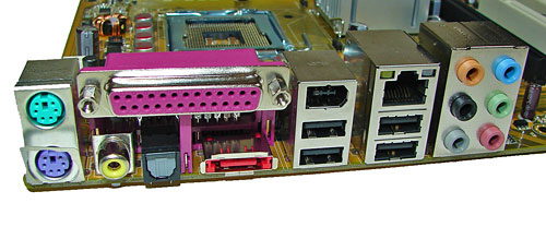
The rear panel contains the standard PS/2 mouse and keyboard, Parallel, LAN, and four USB 2.0 ports. The LAN (RJ-45) port has two LED indicators representing Activity and Speed of the connection through the Attansic L1 Gigabit PCI-E chipset. The audio panel consists of 6 ports that can be configured for 2, 4, 6, and 8-channel audio connections for the ADI 1988A HD codec. The panel also has two S/PDIF (optical out/coaxial out) ports, and an external SATA 3Gb/s port via the JMicron JMB383 chipset.
 |
| Click to enlarge |
After viewing the Abit AB9-Pro, the layout on the ASUS seems almost mundane. However, we have no real complaints about the layout except for the location of the IDE port and 24-pin ATX power connector. We feel like the IDE port connector should have been placed next to the floppy drive connector or replaced it. It would have been nice to have the 24-pin ATX connector located further to the right behind the memory slots. The motherboard was very easy to install and remove from our case. The four fan headers were within easy reach and can be controlled by the Q-Fan utility. The P5B-E replaces the P5B model. We tested both the 1.01G and 1.02G revision level boards and they are identical except for the BIOS changes and a PLL controller. Both boards feature an excellent three-phase voltage regulator power design along with high quality capacitors that yielded exceptional stability.
The DIMM module slots' color coordination is correct for dual channel setup based upon the premise of installing DIMMs in the same colored slots for dual-channel operation. The memory modules are slightly difficult to install with a full size video card placed in the PCI Express x16 slot. The 24-pin ATX power connector is located along the edge of the board along with a series of capacitors for the memory modules. We would have moved the 24-pin ATX connector to the upper right corner of the board to allow for easier access to the memory modules and CPU area in our case. It would also help to facilitate installation of PSUs with cables that are not longer than normal.
The four primary Intel ICH8R SATA ports are red along with the two secondary ports being black. These ports are conveniently located to the left of the ICH8R Southbridge and right of the battery and IDE port connector. We found the positioning of the SATA ports to be excellent when utilizing either the PCI-E x1 or PCI 2.3 slots. The ICH8R is passively cooled with a low rise heatsink and remained cool to the touch throughout testing.
The black floppy drive connector is located on the edge of the board and should have been switched with IDE port connector, as IDE cables are used far more than floppy cables these days. This switch would have eased installation of the IDE cable when using both the IDE and SATA ports. The clear CMOS jumper is color coded blue and is located in between the floppy drive connector and ICH8R chipset. This jumper was very difficult to use when utilizing a double slot video card. The chassis panel is located at the far left corner of the board.
The board comes with (1) physical PCI Express x16 connector, (3) PCI Express x1 connectors, and (3) PCI 2.3 connectors. The layout of this design offers an excellent balance of expansion slots and provides very good clearance for most of the slots. When utilizing a double slot video card the first PCI slot is physically blocked and cannot be used. However, this still leaves two open PCI slots for use and all three PCI Express x1 slots. The black JMicron SATA port is on the right edge of the board along with the Firewire, COM1, and USB headers.
 |
| Click to enlarge |
Returning to the CPU socket area, we find an ample amount of room for alternative cooling solutions that include most air and water cooling solutions. The Intel P965 MCH chipset is passively cooled with a mid-rise heatsink that did not interfere with any installed peripherals. This heatsinsk kept the MCH temperatures in check so that additional chipset voltage was not a factor in our overclocking tests. ASUS places the 4-pin ATX connector in the upper right section of the board and out of the way of the CPU area.
The rear panel contains the standard PS/2 mouse and keyboard, Parallel, LAN, and four USB 2.0 ports. The LAN (RJ-45) port has two LED indicators representing Activity and Speed of the connection through the Attansic L1 Gigabit PCI-E chipset. The audio panel consists of 6 ports that can be configured for 2, 4, 6, and 8-channel audio connections for the ADI 1988A HD codec. The panel also has two S/PDIF (optical out/coaxial out) ports, and an external SATA 3Gb/s port via the JMicron JMB383 chipset.


62 Comments
View All Comments
JarredWalton - Friday, October 20, 2006 - link
I think that was a temporary glitch where the article went live before the last page's text was updated. Shame on you for skipping straight to the end.... ;)BadThad - Sunday, October 22, 2006 - link
Is the v1.02G Asus P5B-E using all solid capacitors? I read a press release stating that Asus was releasing the "P4B-E Plus" version with all solid caps. Rumor says the "Plus" version will not be sold in the USA.....arrgggggg. Tell me that's not true. I want the solid caps for long-term reliability. I'm wondering if our "Plus" is actually the v1.02G?