Abit AW9D-MAX: When "Beta" MAX is a good thing
by Gary Key on September 8, 2006 3:10 AM EST- Posted in
- Motherboards
Features and Layout
Abit designed a board that you will either love or hate. If nothing else this board will elicit an hours worth of conversation about the art of layout design along with providing options the customer wants at this time like an additional PCI slot. This board can be looked at as being a little ahead of its time or an experiment gone badly. After using the board for close to a week and installing it in several cases we have to say it has started to grow on us. It could be we were accepting of the minimalist design and learned to live without an additional PCI slot. Maybe in the end we just realized that the performance potential of the board merited an overlook of some design shortcomings.
Although our board is production based, the color scheme is not. Abit has decided to remove all traces of red on the board and go with all black on the PCI and PCI Express slots with a medium blue on the DIMM one and three slots. Overall, the new color scheme gives the board a very clean yet menacing look worthy of the MAX designation. The board features an excellent four-phase power regulation system, all solid aluminium electrolytic polymer capacitors, silent OTES 2 passive cooling system, and seven fan headers under the control of the Abit EQ program.
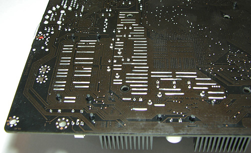
Placed on the back of the board is Abit's OC-Strips system that is designed to dissipate heat away from the board by placing small strips in strategic locations near the CPU socket and MOSFET area. Abit also integrates additional copper layers in between the PCB layers to aid in the extraction of heat from these areas. In an interesting development Abit has also placed eight blue LED diodes at various locations on the back of the board. These diodes can be configured to display differing lighting effects through a bios control panel. It is sort of like revisiting the Disco era when viewing the effects in a dark room.
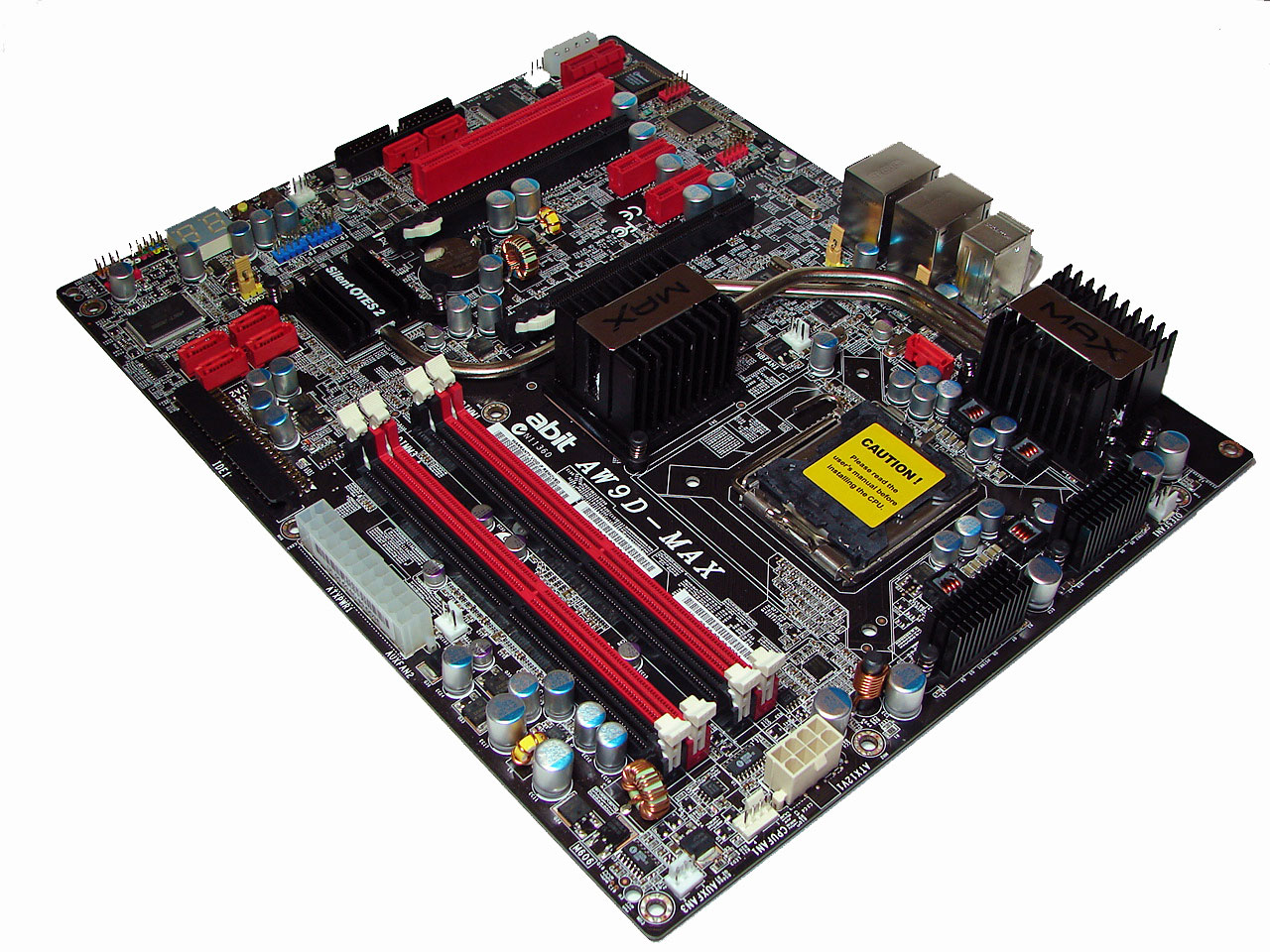
The DIMM module slots' color coordination is correct for dual channel setup. The memory modules are easy to install with a full size video card placed in the first PCI Express X16 slot. The 24-pin ATX connector is conveniently located on the edge of the board in front of the number four DIMM slot. The 8-pin ATX connector is located at the edge of the first DIMM slot. The CPU fan header is located next to the 8-pin ATX plug and due to the size of the CPU area requires your heatsink/fan to be properly oriented if the cable is short.
The Intel ICH7R SATA ports are conveniently located on the board's edge and in front of the single IDE port connector. Unlike other recently reviewed boards the SATA ports are not color coded for primary and secondary operation, though this is a minor concern. We found the positioning of the SATA ports to be very good when utilizing the PCI Express slots or the IDE port connector. When utilizing the second X16 PCI Express slot with a ATI X1900XTX the number one and two ports are difficult to reach.
The chassis panel, CP80P post port debug LED, power on and reset buttons, and fan header are located on the left edge of the board. The yellow clear CMOS block is a traditional jumper design and is easily accessed from its location in front of the uGuru chipset. The ICH7R chipset is passively cooled with the excellent Silent OTES 2 system and we did not notice any thermal issues during overclock testing.
The board comes with two physical PCI Express X16 connectors, two PCI Express X1 connectors, and one PCI 2.3 compliant 32-bit connector along with a dedicated Audio Max connector. The layout of this design in our opinion does not account for the current plethora of PCI cards still in use. Considering this board is geared towards the computer enthusiast one must assume that an ATI CrossFire setup will be a likely consideration which means the single PCI slot will be physically blocked and anyone owning a sound card will be forced to use the on-board solution. A dual slot video card in the first X16 connector will also render the first PCI Express X1 connector physically useless. The black floppy drive connector and 4-pin 12V molex connector are located in inconvenient positions at the edge of the board. The first two SiL3132 SATA ports are located above the floppy drive connector.
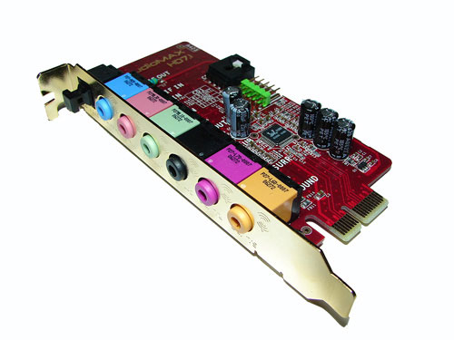
The Audio Max slot that is located next to the molex connector is designed to be used exclusively with the Audio MAX 7.1 riser card featuring the Realtek ALC-882M HD codec.
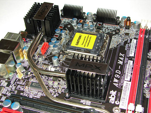
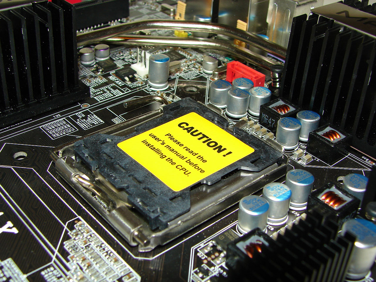
Returning to the CPU socket area, we find an ample amount of room for alternative cooling solutions. We utilized the stock Intel heatsink but also verified several aftermarket cooling systems such as the Thermaltake Big Typhoon, Zalman CNPS9500, Tuniq 120 Tower, and our Scythe Infinity would fit in this area during our tests. Due to the MCH and mosfet heatsink sizes the installation of water-cooling solutions could be problematic in certain cases, although our Cooler Master Aqua Gate system fit fine. Our only concern with water cooling is the heat generated by the MCH causes the heatsink to reach temperatures that can burn your fingers after extended use without the airflow that is normally provided by the CPU and case fans. While the system remained very stable we would highly suggest an active cooling solution for this area if you utilize water-cooling.
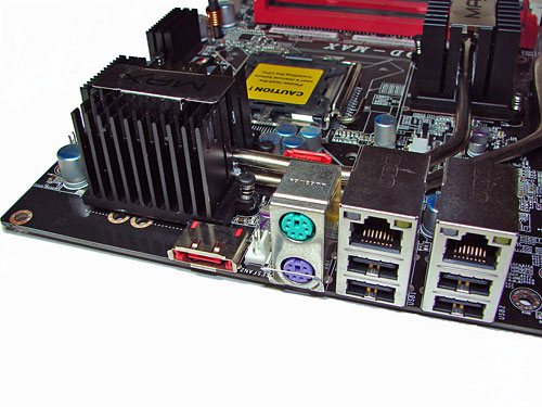
This I/O panel is almost legacy free and if you need a native serial or parallel port then this is not the board for you. The PS/2 mouse and keyboard ports are located to the right of the e-SATA port and fan header. The two LAN (RJ-45) ports and four USB 2.0 connectors are located next to the PS/2 connectors. The LAN (RJ-45) ports have two LED indicators representing Activity and Speed of the connection.
 |
| Click to enlarge |
Abit designed a board that you will either love or hate. If nothing else this board will elicit an hours worth of conversation about the art of layout design along with providing options the customer wants at this time like an additional PCI slot. This board can be looked at as being a little ahead of its time or an experiment gone badly. After using the board for close to a week and installing it in several cases we have to say it has started to grow on us. It could be we were accepting of the minimalist design and learned to live without an additional PCI slot. Maybe in the end we just realized that the performance potential of the board merited an overlook of some design shortcomings.
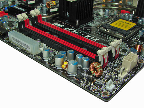
Although our board is production based, the color scheme is not. Abit has decided to remove all traces of red on the board and go with all black on the PCI and PCI Express slots with a medium blue on the DIMM one and three slots. Overall, the new color scheme gives the board a very clean yet menacing look worthy of the MAX designation. The board features an excellent four-phase power regulation system, all solid aluminium electrolytic polymer capacitors, silent OTES 2 passive cooling system, and seven fan headers under the control of the Abit EQ program.
Placed on the back of the board is Abit's OC-Strips system that is designed to dissipate heat away from the board by placing small strips in strategic locations near the CPU socket and MOSFET area. Abit also integrates additional copper layers in between the PCB layers to aid in the extraction of heat from these areas. In an interesting development Abit has also placed eight blue LED diodes at various locations on the back of the board. These diodes can be configured to display differing lighting effects through a bios control panel. It is sort of like revisiting the Disco era when viewing the effects in a dark room.
The DIMM module slots' color coordination is correct for dual channel setup. The memory modules are easy to install with a full size video card placed in the first PCI Express X16 slot. The 24-pin ATX connector is conveniently located on the edge of the board in front of the number four DIMM slot. The 8-pin ATX connector is located at the edge of the first DIMM slot. The CPU fan header is located next to the 8-pin ATX plug and due to the size of the CPU area requires your heatsink/fan to be properly oriented if the cable is short.
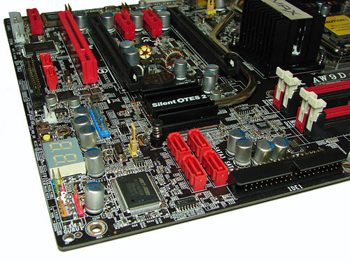
The Intel ICH7R SATA ports are conveniently located on the board's edge and in front of the single IDE port connector. Unlike other recently reviewed boards the SATA ports are not color coded for primary and secondary operation, though this is a minor concern. We found the positioning of the SATA ports to be very good when utilizing the PCI Express slots or the IDE port connector. When utilizing the second X16 PCI Express slot with a ATI X1900XTX the number one and two ports are difficult to reach.
The chassis panel, CP80P post port debug LED, power on and reset buttons, and fan header are located on the left edge of the board. The yellow clear CMOS block is a traditional jumper design and is easily accessed from its location in front of the uGuru chipset. The ICH7R chipset is passively cooled with the excellent Silent OTES 2 system and we did not notice any thermal issues during overclock testing.
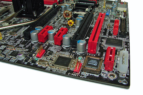
The board comes with two physical PCI Express X16 connectors, two PCI Express X1 connectors, and one PCI 2.3 compliant 32-bit connector along with a dedicated Audio Max connector. The layout of this design in our opinion does not account for the current plethora of PCI cards still in use. Considering this board is geared towards the computer enthusiast one must assume that an ATI CrossFire setup will be a likely consideration which means the single PCI slot will be physically blocked and anyone owning a sound card will be forced to use the on-board solution. A dual slot video card in the first X16 connector will also render the first PCI Express X1 connector physically useless. The black floppy drive connector and 4-pin 12V molex connector are located in inconvenient positions at the edge of the board. The first two SiL3132 SATA ports are located above the floppy drive connector.
The Audio Max slot that is located next to the molex connector is designed to be used exclusively with the Audio MAX 7.1 riser card featuring the Realtek ALC-882M HD codec.
 |
| Click to enlarge |
Returning to the CPU socket area, we find an ample amount of room for alternative cooling solutions. We utilized the stock Intel heatsink but also verified several aftermarket cooling systems such as the Thermaltake Big Typhoon, Zalman CNPS9500, Tuniq 120 Tower, and our Scythe Infinity would fit in this area during our tests. Due to the MCH and mosfet heatsink sizes the installation of water-cooling solutions could be problematic in certain cases, although our Cooler Master Aqua Gate system fit fine. Our only concern with water cooling is the heat generated by the MCH causes the heatsink to reach temperatures that can burn your fingers after extended use without the airflow that is normally provided by the CPU and case fans. While the system remained very stable we would highly suggest an active cooling solution for this area if you utilize water-cooling.
This I/O panel is almost legacy free and if you need a native serial or parallel port then this is not the board for you. The PS/2 mouse and keyboard ports are located to the right of the e-SATA port and fan header. The two LAN (RJ-45) ports and four USB 2.0 connectors are located next to the PS/2 connectors. The LAN (RJ-45) ports have two LED indicators representing Activity and Speed of the connection.


56 Comments
View All Comments
OvErHeAtInG - Sunday, September 10, 2006 - link
...probably to avoid cracking. Yes?yyrkoon - Monday, September 11, 2006 - link
Actually, Its a known issue with some ABIT motherboards, that if you put a metal screws in these holes, it will short the board out. Dont take my word for it though, look around on ABITs forums :)jackylman - Friday, September 8, 2006 - link
Abit also integrates additional cooper layers in between the PCB layers to aid in the extraction of heat from these areas.OvErHeAtInG - Friday, September 8, 2006 - link
While we're picking nits:The 24-pin ATX connector is conveniently located on the edge of the board in front of the number four DIMM slot. The 12-pin ATX connector is located at the edge of the first DIMM slot. The CPU fan header is located next to the 12-pin ATX plug and due to the size of the CPU area requires your heatsink/fan to be properly oriented if the cable is short.
Am I daft, or do you mean 8-pin instead of 12-pin? Sorry if this was already mentioned, I skimmed the comments.
jackylman - Saturday, September 9, 2006 - link
Both typo's fixed. Good job! ;)Gary Key - Sunday, September 10, 2006 - link
I apologize about those errors, using DNS on this article and still do not know how eight became twelve (eight in the charts and my type written text), flat missed catching the other one as that is one word that DNS does not like. ;-)joex444 - Friday, September 8, 2006 - link
you say one of the bios issues was not being able to change the multiplier down, then describe how you went from a 9x to an 8x multiplier... does it allow multiplier changing only with the new bios and the stock one didn't? i don't really care what the stock bios does if i'm going to flash it to the newest one anyways...Gary Key - Friday, September 8, 2006 - link
We could change the multiplier on the X6800 only. We used that chip as stated in the overclocking section to test at 8X and 6X. The issue with the X6800 is that you cannot raise it past 11x. :)johnsonx - Friday, September 8, 2006 - link
You gave us over a half dozen pictures of the board from every angle, but you couldn't toss us a picture of these 'overclocking stripes'? what the hell are they, and how do they work?
Gary Key - Friday, September 8, 2006 - link
A picture of the OC-Strips technology along with additional wording is available now.