The ASRock Z490 Taichi Motherboard Review: Punching LGA1200 Into Life
by Gavin Bonshor on May 27, 2020 9:00 AM ESTPower Delivery Thermal Analysis
A lot more focus has been put onto power delivery specifications and capabilities, not just by manufacturers, but as a result of users demands. In addition to the extra power benefits from things like overclocking, more efficient designs in power deliveries and cooling solutions aim to bring temperatures down. Although this isn't something most users ever need to worry about, certain enthusiasts are bringing more focus onto each boards power delivery. The more premium models tend to include bigger and higher-grade power deliveries, with bigger and more intricate heatsink designs, with some even providing water blocks on ranges such as the ASUS ROG Maximus Formula series.
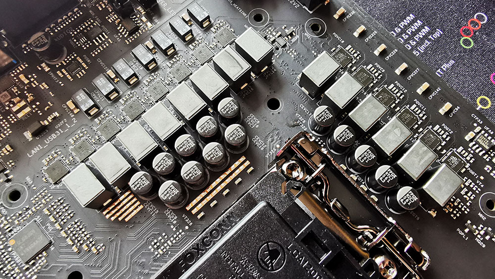
The 12+2 (6+1) power delivery on the ASRock Z490 Taichi
Testing Methodology
Our method of testing out if the power delivery and its heatsink are effective at dissipating heat, is by running an intensely heavy CPU workload for a prolonged method of time. We apply an overclock which is deemed safe and at the maximum that the silicon on our testbed processor allows. We then run the Prime95 with AVX2 enabled under a torture test for an hour at the maximum stable overclock we can which puts insane pressure on the processor. We collect our data via three different methods which include the following:
- Taking a thermal image from a birds-eye view after an hour with a Flir Pro thermal imaging camera
- Securing two probes on to the rear of the PCB, right underneath CPU VCore section of the power delivery for better parity in case a probe reports a faulty reading
- Taking a reading of the VRM temperature from the sensor reading within the HWInfo monitoring application
The reason for using three different methods is that some sensors can read inaccurate temperatures, which can give very erratic results for users looking to gauge whether an overclock is too much pressure for the power delivery handle. With using a probe on the rear, it can also show the efficiency of the power stages and heatsinks as a wide margin between the probe and sensor temperature can show that the heatsink is dissipating heat and that the design is working, or that the internal sensor is massively wrong. To ensure our probe was accurate before testing, I binned 10 and selected the most accurate (within 1c of the actual temperature) for better parity in our testing.
To recreate a real-world testing scenario, the system is built into a conventional desktop chassis which is widely available. This is to show and alleviate issues when testing on open testbeds which we have done previously, which allows natural airflow to flow over the power delivery heatsinks. It provides a better comparison for the end-user and allows us to mitigate issues where heatsinks have been designed with airflow in mind, and those that have not. The idea of a heatsink is to allow effective dissipation of heat and not act as an insulator, with much more focus from consumers over the last couple of years on power delivery componentry and performance than in previous years.
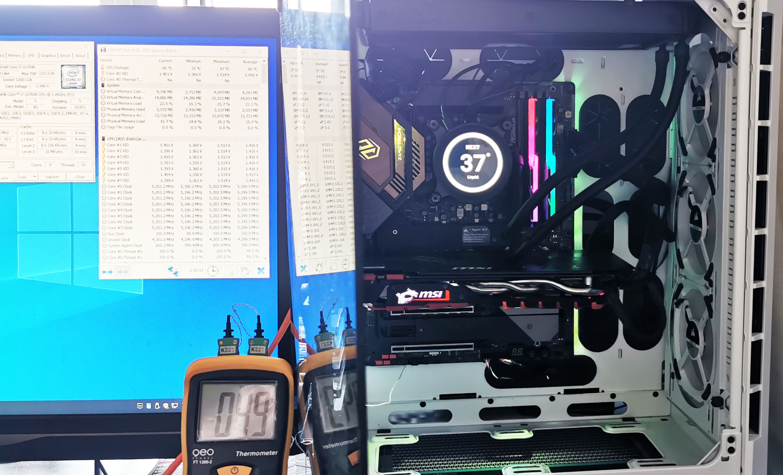
ASRock Z490 Taichi undergoing our VRM thermal testing (we close the side panel when testing)
For thermal image, we use a Flir One camera as it gives a good indication of where the heat is generated around the socket area, as some designs use different configurations and an evenly spread power delivery with good components will usually generate less heat. Manufacturers who use inefficient heatsinks and cheap out on power delivery components should run hotter than those who have invested. Of course, a $700 flagship motherboard is likely to outperform a cheaper $100 model under the same testing conditions, but it is still worth testing to see which vendors are doing things correctly.
Thermal Analysis Results

We measured 51.3°C on the hottest part of the PCB around the power delivery
The ASRock Z490 Taichi is using a 12+2 phase power delivery which is controlled by an Intersil ISL69269 PWM controller operating at 6+1. The power delivery is using twelve Vishay SIC654 50 A power stages for the CPU, with six ISL6617A doublers, while the SoC section is using two Vishay SIC654 50 A power stages and a single ISL6617A doubler.
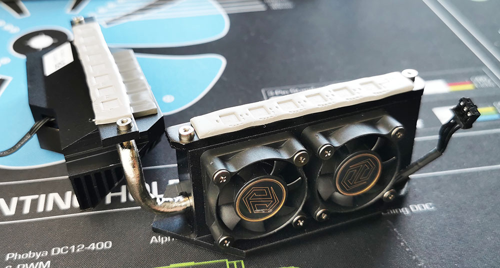
The ASRock Z490 Taichi uses an actively cooled VRM heatsink
Keeping the power delivery cool, ASRock has integrated a pair of small cooling fans designed to push airflow through the aluminium fins on the heatsink. ASRock has given the user full control over fan curves and settings for these fans, which when left on the original BIOS (1.30A) it came with, we're very noticeable in terms of noise levels. ASRock has since patched this via a firmware update (1.50) and opted for a more subtle and less aggressive fan curve which balances out heat versus noise levels.
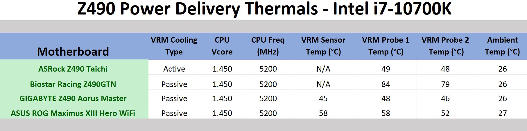
Using our VRM thermal testing methodology, the ASRock Z490 Taichi performs well which is expected due to the actively cooled VRM heatsink. As the ASRock Z490 Taichi doesn't include a dedicated temperature sensor for the power delivery, we were at the mercy of our probes which outputted temperatures of 49°C on the first probe, and 48°C on the second. Taking the tempered glass panel off our test chassis and taking a thermal image, we observed a maximum of 51.3°C on the hottest part of the motherboard, which was in the corner between the CPU and SoC sections of the power delivery. Compared directly to the GIGABYTE Z490 Aorus Master which ran marginally cooler, albeit, with an 8+1 design, we expect the Z490 Taichi power delivery to run a little warmer when the two cooling fans are disabled.


57 Comments
View All Comments