DFI 748-AL: First Look at SiS 748
by Wesley Fink on August 30, 2003 12:00 AM EST- Posted in
- Motherboards
DFI 748-AL: Board Layout
Click image to view a larger picture.
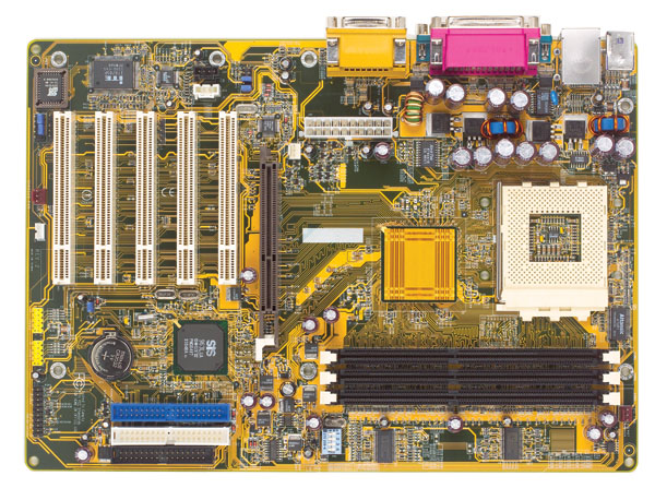
The DFI 748-AL is a less than full-size board, which we often see in boards designed to sell at lower prices, but it does not feel cramped in any way. 7 standoffs are used to mount the board to the case. It generally has a good layout, especially considering the smaller size of the board, and the price it is selling for.
Click image to view a larger picture.
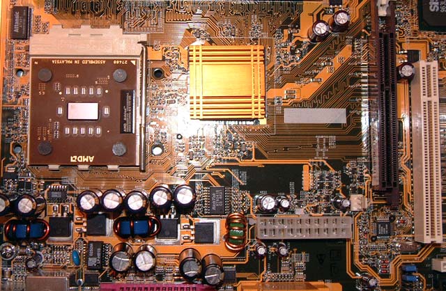
One location we are particular about is the ATX (20-pin) connector position, because the cable is very bulky and difficult to connect if poorly placed. The 748-AL ATX connector is located near the midline of the PCB to the left of the CPU socket. This is a common place for the ATX connector, but it is one of worst locations possible for the end-user. This means you have to snake the bulky 20-pin cable either around your CPU or over it. This location can also obstruct the installation/uninstallation of the CPU, CPU HSF, and possibly memory modules, depending on case design. We prefer a right of CPU upper position for the 20-pin connector, since this works well in most case designs. There is not an additional 4-pin 12V connector on the 748-AL. This optional power connection is starting to appear on many Athlon boards, but is not used on the 748-AL. The SiS 748 reference board did not use the 4-pin 12V either, so it’s not likely the 4-pin 12V will be seen on any 748 boards.
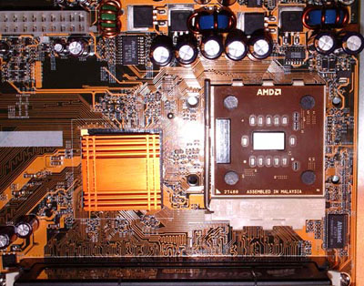
The space around the CPU and north bridge is very important if you plan to mount larger heatsink/fans or water-cooling solutions. As you can see, DFI has kept this area clean and clear on the 748-AL. It’s also a pleasant surprise to find the 4 holes around the CPU for large heavy HSFs from Alpha, Swiftech, Thermalright, OCZ and others. Fans of water-cooling will also be pleased to see the 4 holes for mounting some of the water-block solutions.
The 3 dimm sockets support the maximum 3GB available with the SiS 748 chipset. The arrangement on the DFI 748-AL is also excellent, making it very easy to add and remove memory without having to remove your video card. There is very little to complain about in the arrangement of this area.
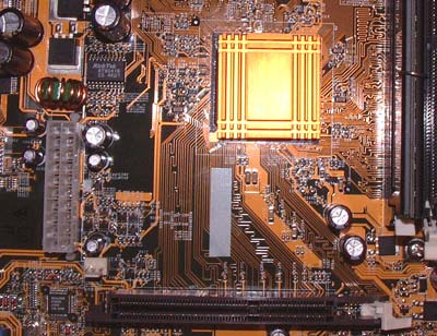
As often seen on boards designed to sell at a low price, the north bridge heatsink is shallow and small. While it was perfectly adequate for normal operation, we found that the north bridge became very warm in the large overclocks possible with this board. This caused us some problems in our overclock stress testing. If this board will be used for squeezing performance from your Athlon, then we would suggest you replace the stock north bridge with a more effective passive or active cooling solution. There is a 3rd fan header, colored white, near the 20-pin ATX connector for active solutions, but you will have to watch weight as the north bridge cooler must be mounted with tape or thermal epoxy.
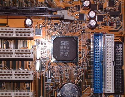
One problem with smaller boards is it is usually impossible to place the IDE connectors and Floppy connectors in the best upper right location behind the dimm sockets. Considering the available options, DFI has wisely place the IDE/Floppy connectors just below mid and to the right of the board. Some thought went into this, because the connectors are completely clear of the AGP 8X slot, and some of the largest cards you will see in today’s designs are video cards. The Primary and Secondary IDE connectors are, in our opinion, best located above the midsection of the motherboard and to the right of the DIMM slots, which allows the standard bundled IDE cables to reach the upper bays of an ATX case. This means you will be able to install optical drives in the 1st and 2nd bays. This location also allows better air flow and case organization to be possible and allows the user to make use of the Slave connector on the bundled IDE cables. While the 748-AL does not use the ideal position, the IDE/Floppy connectors are in a good location considering the options available.
The DFI 748-AL floppy connection is placed with the IDE connectors to the far right just below midline. This location might be a challenge for case designs with the floppy drive at the top of the case, but it should work fine for most case arrangements. At least we don’t find a floppy connector at the bottom of the board, which is often a nightmare.
![]()
The DFI 748-AL has 5 PCI slots for expansion cards and an 8X AGP slot. Considering the options already on board the 748-AL and the mainstream market it will sell to, this should be plenty of expansion options. The AGP/PCI slots are well arranged and are clear of the 3 Dimm slots. There is plenty of room for adding and removing memory modules without interfering with the AGP card.
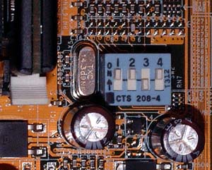
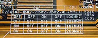
Almost every motherboard these days defaults to automatic CPU setup. This can be useful, but it can also be a handicap if, for instance, you have a Barton 2500+ that runs just fine as a 3200+ at default voltage. DFI considered that possibility with the 748-AL, and you can go with default CPU settings or force 100,133,166, or 200FSB with a Dip switch. Settings for the switch are silk-screened on the motherboard.


22 Comments
View All Comments
Anonymous User - Saturday, August 30, 2003 - link
too little, too late.dvinnen - Saturday, August 30, 2003 - link
yay, SIS!Now lets bust out the ALi chipsets