AnandTech Power Supply Test Methodology
by Christoph Katzer on July 12, 2007 12:00 AM EST- Posted in
- Cases/Cooling/PSUs
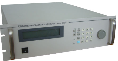
Chroma Programmable AC Source 61604
In most parts of the world it is usual to use a grid power of 230VAC with a frequency of 50Hz. In the US, Canada, and parts of South America however the standards are around 117VAC with a frequency of 60Hz (commonly rounded to 120VAC). To provide our readers the maximum range the units can handle, we are testing power supplies with multiple inputs in these different voltage ranges.
The difference in the DC output between 110VAC and 120VAC is marginal, but from 120VAC to 230VAC it's another story. Lower input voltage results in a higher energy usage by the power supply, and higher power usage lowers the efficiency of each power supply. Therefore we will see differences between tests at 115VAC and those at 230VAC. By covering these two different input voltages of 115VAC and 230VAC we will offer a good variety for all our readers and we will provide the only current public tests conducted at both input voltages.
The Chroma model 61604 is capable of providing 0 - 300VAC with a power up to 2000 volt-amperes (VA). The output frequency can be selected between 15Hz and 1000Hz. To simulate a perfect environment we use 50Hz for the test with 230VAC and 60Hz for 115VAC, which is what users generally find at the power grid in various countries.
However, our AC Source actually provides two functions. The first is that it acts as a normal AC Source, allowing us to test with different voltages. Second, it is also a power meter that gives us important data like power usage and power factor.
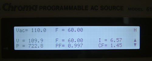
The display shows us several important numbers. The top row contains information regarding the power that we want the device to deliver. The two lower rows display the actual delivered voltage, power consumption from the power grid, frequency, power factor, current and the crest factor. For our tests the most important items are the voltage, frequency, power consumption and power factor. In our reviews we will include a graph which will show the energy loss from the power supply during testing as follows.
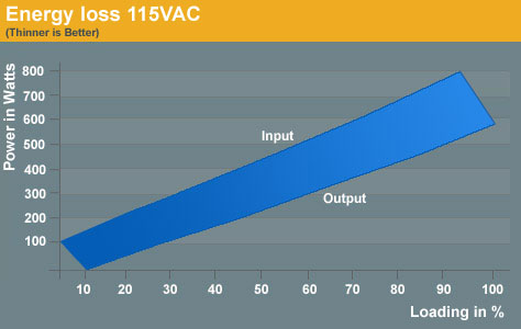
Sample Energy Loss
The upper line marked with Input is the actual power drawn from the power grid. The line below marked with Output is the DC power which is given to the PC. Usually at lower power draws from the system the power loss will be lower as well. This can be seen by the increasing distance between the two lines, which grows steadily with increasing power usage.
By loading a power supply at a specific level, we get both the power input and the power output. Dividing these two units gives the efficiency of each tested power supply. Efficiency has become a modern benchmark for power supplies and many companies build their complete marketing strategy on high efficiency. To make this efficiency readable we will use a graph which shows each step at a specific point of load. To get the best overall impression of a power supply we decided to test in steps of 10% of the actual load each power supply is able to deliver. The load of each rail is calculated in conformity with the Power Supply Design Guide V1.1 released by Intel in March of this year.
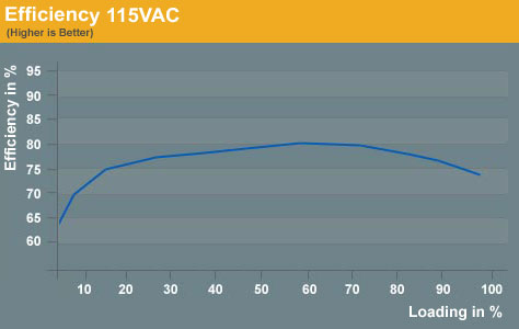
Sample Efficiency
The efficiency is normally displayed in a curve which starts at a low point around 60 to 70%. With increasing loads the curve will usually reach its zenith at 50% to 70% of the maximum load the power supply can handle. This means that at this point the power supply has its best efficiency and ideally it should spend most of its time running in this area. High loads push the power supply beyond this point to where the curve is normally heading down again.
The important thing to take away from this is that it's not easy to buy a perfect power supply for the home PC and a little bit of calculation needs to be done. Remember that the power supply should not run at lower or higher loads most of the time. The former happens when a user buys a power supply that provides more potential power than they need, while the latter occurs when users purchase power supplies that meet their minimum requirements. This is information that many marketing departments aren't interested in disseminating, however, and some companies are advertising power supplies rated at more than 1000W - something which few if any PCs will need at the moment.
In most parts of the world it is usual to use a grid power of 230VAC with a frequency of 50Hz. In the US, Canada, and parts of South America however the standards are around 117VAC with a frequency of 60Hz (commonly rounded to 120VAC). To provide our readers the maximum range the units can handle, we are testing power supplies with multiple inputs in these different voltage ranges.
The difference in the DC output between 110VAC and 120VAC is marginal, but from 120VAC to 230VAC it's another story. Lower input voltage results in a higher energy usage by the power supply, and higher power usage lowers the efficiency of each power supply. Therefore we will see differences between tests at 115VAC and those at 230VAC. By covering these two different input voltages of 115VAC and 230VAC we will offer a good variety for all our readers and we will provide the only current public tests conducted at both input voltages.
The Chroma model 61604 is capable of providing 0 - 300VAC with a power up to 2000 volt-amperes (VA). The output frequency can be selected between 15Hz and 1000Hz. To simulate a perfect environment we use 50Hz for the test with 230VAC and 60Hz for 115VAC, which is what users generally find at the power grid in various countries.
However, our AC Source actually provides two functions. The first is that it acts as a normal AC Source, allowing us to test with different voltages. Second, it is also a power meter that gives us important data like power usage and power factor.
The display shows us several important numbers. The top row contains information regarding the power that we want the device to deliver. The two lower rows display the actual delivered voltage, power consumption from the power grid, frequency, power factor, current and the crest factor. For our tests the most important items are the voltage, frequency, power consumption and power factor. In our reviews we will include a graph which will show the energy loss from the power supply during testing as follows.
Sample Energy Loss
The upper line marked with Input is the actual power drawn from the power grid. The line below marked with Output is the DC power which is given to the PC. Usually at lower power draws from the system the power loss will be lower as well. This can be seen by the increasing distance between the two lines, which grows steadily with increasing power usage.
By loading a power supply at a specific level, we get both the power input and the power output. Dividing these two units gives the efficiency of each tested power supply. Efficiency has become a modern benchmark for power supplies and many companies build their complete marketing strategy on high efficiency. To make this efficiency readable we will use a graph which shows each step at a specific point of load. To get the best overall impression of a power supply we decided to test in steps of 10% of the actual load each power supply is able to deliver. The load of each rail is calculated in conformity with the Power Supply Design Guide V1.1 released by Intel in March of this year.
Sample Efficiency
The efficiency is normally displayed in a curve which starts at a low point around 60 to 70%. With increasing loads the curve will usually reach its zenith at 50% to 70% of the maximum load the power supply can handle. This means that at this point the power supply has its best efficiency and ideally it should spend most of its time running in this area. High loads push the power supply beyond this point to where the curve is normally heading down again.
The important thing to take away from this is that it's not easy to buy a perfect power supply for the home PC and a little bit of calculation needs to be done. Remember that the power supply should not run at lower or higher loads most of the time. The former happens when a user buys a power supply that provides more potential power than they need, while the latter occurs when users purchase power supplies that meet their minimum requirements. This is information that many marketing departments aren't interested in disseminating, however, and some companies are advertising power supplies rated at more than 1000W - something which few if any PCs will need at the moment.


49 Comments
View All Comments
tynopik - Tuesday, July 17, 2007 - link
please please please add brownout/sag/powerdip/flicker tests!this is a big killer of power supplies and personally caused one of mine to blow up and take out everything connected to it (mb, 3 hd, cd, etc)
test how it maintains power when the voltage drops down to 90v
test how it responds to a series of flickers (this is what killed mine)
gold standards in PSU review
jonnyguru.com
silentpcreview.com
mcvan - Friday, July 13, 2007 - link
This looks like an ambitious effort with lots of good test gear, but the thermal and acoustic aspects of the testing setup are seriously flawed.1) A 1 meter cube box is a *horrific* acoustic test environment. It's way too small to avoid boundary effects. All the acoustic stuffing in the world will not help. You can see in the photo that the mic has to be at one corner and the PSU in the other corner to have 1m distance. Ever stand in the corner to sing? Notice what happens to your voice?
The box will impose its very significant acoustic signature on everything they measure or record in there. The most important effect will be boosts in all the freq below ~500Hz, along with peaks in certain bass frequencies. Any fan used in any PSU will excite such resonances.
Also, there's no indication of what ambient noise level you're getting in there with the Chroma testers going. You mentioned 15 dBA -- I say no way, not with the Chroma machines going. I actually bought a similar AC source device a few years ago and had to abandon it due to the noise problem -- it easily reached 60 dBA @1m. For their test box to achieve 15 dBA ambient with the Chroma machines going in the same room, the box would have to have something like >35 dBA noise isolation and/or the room would have to be gigantic (so that the Chroma machines could be far away.... which then brings up the problem of cable resistance). The former requires astonishing acoustic technology and knowhow; judging by the box construction details, I question whether you can get anywhere near that kind of noise isolation, and if the test room was that big, you'd have said so.
2) The PSU will be in the 1m test box more or less by itself. The box will be sealed during testing. This is unrealistic for 2 reasons --
A) a PSU in a real PC always see some fresh air intake, and
B) it also sees at least some of the heat produced by the components it is feeding.
To expand on this further, the DC output of the PSU goes to components that heat up. These components are in the same case as the PSU, and they affect the ambient temperature of the PSU. It's a simple fact that the total heat generated in the computer is equal to its AC power consumption. Case fans obviously affect the overall thermal situation for the PSU, but the PSU's cooling fan draws air from inside the case. Unless the PSU is in a separate chamber with its own intake vent, it has to deal with not only the heat generated within itself as a result of AC/DC conversion losses, but also at least some of the heat from the components it powers. Heat can affect a PSU's max power output capacity, its stability, and of course, its fan speed/noise.
It's because Anandtech is trying to do "serious" acoustic testing that all this becomes important. In http://www.silentpcreview.com/article683-page1.htm...">SPCR's PSU testing, we have a very clear operational model: The test rig is a close facsimile of a quiet enthusiast's low airflow, low airflow-impedance system. Your test setup doesn't resemble any real system -- there is no fresh air intake, and the exhaust heat goes nowhere. Can such a test setup tell anything practical and worthwhile about the noise/load or the heat/load behavior of any PSU? Certainly not if you intend to install that PSU in a case where there are case fans, intake vents, and other components that also get hot.
I also see another serious thermal issue: It seems to me that in your setup, once a certain amount of heat has been generated inside, continued testing can only lead to continually rising temperature for any PSU. In other words, the temperature/load relationship will be dictated almost entirely by how LONG the PSU is kept running. The heat is trapped in the box; it has nowhere to go, and the box is well insulated. Even at a modest 100W load, leave it running in that test box for a few hours, and I'd bet $$ almost any PSU will shut down due to overheating. So where in the rising curve (over time) could you say is the right point to look at temperature or fan speed or noise? This is a challenging problem.
This is completely different from SPCR's test rig. We generally try to do all the PSU testing at the same room temperature (20~22C), which we can maintain most of the year -- we don't do PSU testing on hot July and August days. This does not stop the internal temperature of the test rig from reaching upwards of 50C at high power load. Importantly, at almost any load level with almost any PSU, the system does come to an equilibrium where temperature (in and out), fan speed and noise stabilize. This is then the obvious point to stop and take measurements.
Furthermore, in the SPCR test rig, almost any well-built PSU can be run at >75% of rated power indefinitely without overheating, which I think cannot be true of your current setup in that sealed box. (I wanted to say 100%, but I suspect this is not true -- even some of the well-built PSUs may overheat at full load if left at full load long enough.) All this is to say that our test rig has predictable thermal characteristics that do closely resemble a real PC system, which is very important if you want to do accurate acoustic testing / analysis. It's also very important for thermal analysis.
Christoph Katzer - Monday, July 16, 2007 - link
Hey Mike,You can be sure your concern will be taken into account. First of all the box isn't just 1m. It just looks like this on the pictures but an extension is already planned since we also want to fit chassis inside. The PSU and Mic have enough room to the sides and yes, we separated the Chroma and the PSU that much from each other that we can test just fine. As said currently we are still working on the audio part but the box like it is brought us far until now.
We will have both room-temp and 50°C from the next review on since we think it is important to show what a PSU can handle. We don't know where the PSU is running later thus we present as many results possible that our readers have enough information to form an own opinion.
Christoph Katzer - Friday, July 13, 2007 - link
Thanks for all your comments and suggestions. You can be sure that it will all be taken into account and we are working on it right now.giantpandaman2 - Friday, July 13, 2007 - link
Could you test what happens to the power supply when there's a sudden drop in voltage and then a surge back to normal? I figure that'd emulate someone turning on, say, a heater on the same circuit?Now, I know a lot of people will say only an idiot would ever plug a computer with other appliance that have high power draw...well...sometimes we have to build computers for people who are a bit, how should we say, technically challenged. WOuld be nice to know if there are any foolproof PSU's for those situations.
langenbacher - Thursday, July 12, 2007 - link
The way in which a power supply acts at power-up and power-down can be very important. These guys publish specifications for PS's that include timing specifications for this.http://ssiforum.org">http://ssiforum.org http://ssiforum.org/specifications.aspx#powerSuppl...">http://ssiforum.org/specifications.aspx#powerSuppl...
http://www.formfactors.org">http://www.formfactors.org http://www.formfactors.org/developer%5Cspecs%5CPSU...">http://www.formfactors.org/developer%5Cspecs%5CPSU...
I need power supplies that "boot up" and shut down cleanly, in order to test my company's products to see that they meet spec for their own behavior at power-up and power-down time. Some power supplies that have been highly rated in the press have ugly ramp-up voltage waveforms that make it impossible for me to make measurements on our PCI-X and PCI-E boards.
I have seen how bad things can happen on a PCI bus if power-up doesn't go right, most commonly failure for devices to properly initialize and enumerate on the bus.
In the case of the "bad" power supplies I got, it was easy to see with an oscilloscope that the voltage did not ramp up cleanly, and it wasn't even necessary to know the official specs to see that something was wrong. I think that simply capturing a trace showing all the voltages ramp up and ramp down should be able to weed out the worst offending power supplies.
erikpurne - Thursday, July 12, 2007 - link
I'm no expert on these things, but I can see that PSUs would be a very difficult component to test in a meaningful way, and though there are a few things your setup appears to overlook, you've done an awesome job of putting together a rig that can do it as well as can reasonably be expected (once you get the ripple measurements figured out). Must have cost a bundle, but there's little doubt that this will make AT the world's #1 source for PSU info. And that anechoic chamber/box/whatever will come in handy for getting accurate SPL measurements from a whole bunch of other stuff, too! I just hope a PSU doesn't decide to explode or catch fire inside your nifty box and ruin it...Also, I assume you'll only be using the box for relatively quick sound measurements and not for the actual load testing. If not, how will you deal with the rapidly and indefinitely - till something fails - rising temps inside the extremely well insulated box? I mean, hooray for stress testing, but wouldn't that get a little extreme?
Either way, props on doing it right or not at all.
erikejw - Thursday, July 12, 2007 - link
"To measure the produced noise we have build an anechoic room in which we can measure the noise down to just 15 dB(A)."Please use this when you test fans too, it would rock.
Looking forward to this series of tests too.
Conky - Thursday, July 12, 2007 - link
This is long overdue. No more relying on lesser sites for PSU info. :)markitect - Thursday, July 12, 2007 - link
You should add a few additional temps to determine the robustness of the power supply.First:
Check stable outputs during different levels of short and long term power brown outs and surges. (handles 1 sec at 250V things like that.
Second:
check stability as temp gets out of control.
Raise the ambient temp to see if the output changes as the temp increases. Power supplies tend to suck air from the case so it could see cool-side temps up to 50C