ASRock Z77 Extreme6 Review: Legacy Bites Back
by Ian Cutress on July 13, 2012 2:00 PM EST- Posted in
- Motherboards
- ASRock
- Z77
ASRock Z77 Extreme6 In The Box
ASRock boxes seem to flip-flop between being very good and not that good. The appeal inside the box should outweigh the assumed contents given the price - if you can tool up a $100 motherboard package with what we would assume a $200 package would contain then you are in the clear.
Rear IO Panel
Quick Installation Guide
Software Setup Guide
Driver CD
Four SATA Cables
3-slot fixed SLI Bridge
Front USB 3.0 Panel + SSD Holder
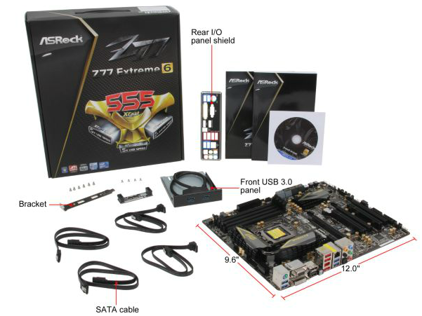
One jewel in ASRock's crown is the smart USB front panels they stick in their box. The first board I ever reviewed for P67, the ASRock P67 Extreme4, came with it in a very well priced package. The Z77 Extreme6 comes in more expensive than that board, so by default we should expect it here, and we do (which is a good thing). Even though very few other manufacturers have it, what other manufacturers do have often is a full complement of SATA cables - despite having 8 SATA ports on board ASRock choose only to put four cables in the box.
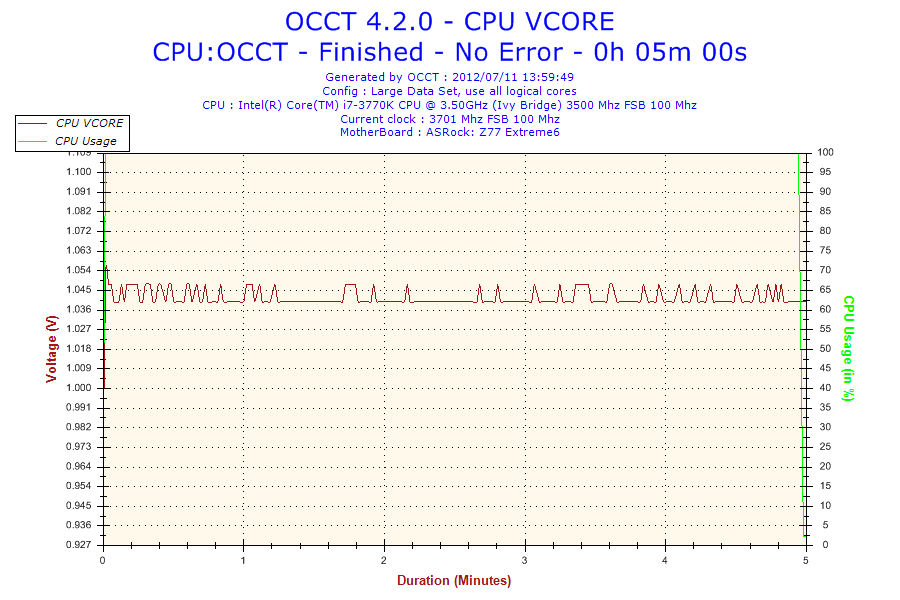
Voltage Readings
After my first publication of OCCT voltage readings, a few readers responded with a more in-depth reasoning behind some of the results we were seeing. With this in mind, I would like to re-describe what we are doing with this test, and how it comes about.
Much of what an enthusiast overclocker does is monitor CPU temperature and voltage. Whatever settings a user places in the BIOS or OS is at the mercy of the motherboard - in terms of actually setting the values and reporting the values back. As an enthusiast, we have to rely on what readings we get back, and hope that motherboard manufacturers are being honest with their readings.
Take CPU voltage. What we as a user see in CPU-Z or OCCT is a time-averaged value that hides voltage ripple (if any) for power delivery. It is very easy for a motherboard manufacturer to hide this value, or to disregard slight deviations and report a constant value to the user. The CPU voltage reading can be taken at a variety of places on the power plane, which can vary between motherboards and manufacturers, meaning that each reading is essentially not comparable with the other. Nevertheless, as an enthusiast, we will constantly compare value A with value B.
Whether or not I can achieve 4.7 GHz with 1.175 volts on a particular board is inconsequential - your motherboard may perhaps produce the same result with a reading at 1.200 volts. The only way to test the actual value is with consistent methodology is via an oscilloscope connected to similar points on each board. This may sound like taking an OCCT reading is therefore redundant.
However, motherboards have settings relating to load line calibration. As load is applied to the CPU, the voltage across the processor decreases (VDroop). Load Line calibration essentially attempts to control this level of droop, by increasing voltage when voltage drops are detected away from a fixed value. Manufacturers have different ideas on how to modify LLC with respect to load, or whether the level of modification should be controlled by the user. Some manufacturers offer the option at a variety of levels, such that overclockers can be sure of the applied setting (even if it increases peak voltage, as explained by AnandTech in 2007).
By doing a full load OCCT test, we are essentially determining both how aggressive the motherboard is reporting the CPU voltage under load and how aggressive load line calibration is performing (from the point of view of the user without an oscilloscope or DVM). If someone has one of the motherboards we have tested and you have a different one, variations in load voltage should describe the offset you may require for overclock comparisons.
| Reported Load Voltage / V | |
| ASRock Fatal1ty Z77 Professional | 0.956 |
| ASRock Z77 Extreme4 | 1.050-1.058 |
| ASRock Z77 Extreme6 | 1.040-1.048 |
| ASUS P8Z77-V Deluxe | 1.085 |
| ASUS P8Z77-V Pro | 1.090 |
| Gigabyte Z77X-UD3H | 1.067 |
| MSI Z77A-GD65 | 1.020 |
Overclocking
Note: Ivy Bridge does not overclock like Sandy Bridge. For a detailed report on the effect of voltage on Ivy Bridge (and thus temperatures and power draw), please read Undervolting and Overclocking on Ivy Bridge.
Our standard overclocking methodology is as follows. For automatic overclocks options, they are selected and tested for stability with PovRay and OCCT to simulate high-end workloads and catch any immediate causes for memory or CPU errors.
For manual overclocks, based on the information gathered from previous testing, starts off at a nominal voltage and CPU multiplier, and the multiplier is increased until the stability tests are failed. The CPU voltage is increased gradually until the stability tests are passed, and the process repeated until the motherboard reduces the multiplier automatically (due to safety protocol) or the CPU temperature reaches a stupidly high level (100ºC+).
Our test bed is not in a case, which should push overclocks higher with fresher (cooler) air. We also are using Intel's All-in-one Liquid Cooler with its stock fan. This is a 120mm radiator liquid cooler, designed to mimic a medium-to-high end air cooler.
Automatic Overclock:
Options for automatic overclocking are found in the BIOS. We have the main option, 'Advanced Turbo 30' which implements a 4.7 GHz overclock, and a second option 'Optimized CPU OC' that gives a series of options from 4.0 GHz to 4.8 GHz in 200 MHz increments.
Advanced Turbo 30 sets the BIOS to give 4.7 GHz to all cores at load. The setting enables PLL Overvoltage, and applies the following settings:
CPU Voltage: +0.085 volts
CPU Load Line Calibration: Level 1
iGPU Voltage: +0.120 volts
iGPU Load Line Calibration: Level 2
With these settings, the OS reported a voltage at load of 1.280 volts. Temperatures were very high, showing a peak temperature of 97ºC during PovRay and 98ºC during OCCT. It should be noted that the VRM heatsinks were barely warm to the touch.
For the Optimized CPU OC, the following results were obtained:
At the 4.0 GHz setting, the BIOS was set to 40x multiplier on all cores, CPU voltage set to Auto and LLC was set to Auto. In the OS, it showed 1.096 volts at full CPU load, giving maximum temperatures of 65ºC during PovRay and 66ºC during OCCT.
At the 4.2 GHz setting, the BIOS was set to 42x multiplier on all cores, CPU voltage set to Auto and LLC was set to Auto. In the OS, it showed 1.096 volts at full CPU load, giving maximum temperatures of 67ºC during PovRay and 68ºC during OCCT.
At the 4.4 GHz setting, the BIOS was set to 44x multiplier on all cores, CPU voltage set to Auto and LLC was set to Auto. In the OS, it showed 1.096 volts at full CPU load, giving maximum temperatures of 68ºC during PovRay and 70ºC during OCCT.
At the 4.6 GHz setting, the BIOS was set to 46x multiplier on all cores, CPU voltage set to Auto and LLC was set to Level 1. In the OS, it showed 1.192 volts at full CPU load, giving maximum temperatures of 80ºC during PovRay and 82ºC during OCCT.
At the 4.8 GHz setting, the BIOS was set to 48x multiplier on all cores, CPU voltage set to 1.240 volts fixed and LLC was set to Level 1. In the OS, it showed 1.248 volts at full CPU load, giving maximum temperatures of 93ºC during PovRay and 96ºC during OCCT.
Manual Overclock:
For the manual overclock, given the results seen in the automatic overclocking, we started at 1.100 volts on the CPU and a 45x multiplier.
At the 45x multiplier and 1.100 volts, the computer failed to load Windows correctly. We subsequently adjusted the LLC from Auto to Level 1, which caused a successful boot and was stable during testing. The following results were achieved.
For 4.5 GHz, the minimum CPU voltage stable set in the BIOS was at 1.100 volts, and the CPU multiplier to 45x. This was stable in the OS, showing 1.096 volts at load and giving peak temperatures of 69ºC during PovRay and 70ºC during OCCT.
For 4.6 GHz, the minimum CPU voltage stable set in the BIOS was at 1.125 volts, and the CPU multiplier to 46x. This was stable in the OS, showing 1.128 volts at load and giving peak temperatures of 73ºC during PovRay and 75ºC during OCCT.
For 4.7 GHz, the minimum CPU voltage stable set in the BIOS was at 1.175 volts, and the CPU multiplier to 47x. This was stable in the OS, showing 1.160 volts at load and giving peak temperatures of 81ºC during PovRay and 82ºC during OCCT.
For 4.8 GHz, the minimum CPU voltage stable set in the BIOS was at 1.250 volts, and the CPU multiplier to 48x. This was stable in the OS, showing 1.254 volts at load and giving peak temperatures of 94ºC during PovRay and 95ºC during OCCT.
For 4.9 GHz, we were unable to find a minimum stable voltage before hitting 100ºC during testing. At 1.300 volts, the system reached 100ºC during PovRay and still crashed the system.


35 Comments
View All Comments
albiglan - Friday, July 13, 2012 - link
I liked the parts about the difficulty in reviewing motherboards and the explanation of the humidity feature. (Overclocking could maybe have benefited from a table layout)Would be nice to see additional benchmarks for things not directly related to performance (something that covers things like ease of setup, stability, etc. that is easy to compare against other mobos...)
IanCutress - Friday, July 13, 2012 - link
I have a board on the test bed now that was a little different to set up - all the additional controllers had to be installed one by one. Every other board manufacturer usually has a one button install for drivers and software. Odd.It is hard to benchmark stability. We don't have infinite CPUs to keep all the boards running for days. I only have one CPU, and when one motherboard is tested I move it on to the next one. All I can do are my PovRay/OCCT tests to make sure it won't fall over in the first five minutes or so. I'm sure there are owners of these boards (like cknobman) who have been using these boards in a real world context that can give you a hint as to how they feel about their boards :)
Ian
xodius80 - Friday, July 13, 2012 - link
please anand, its time to move into the future of computing, we need a floppy port benchmark to see how well the chipset handles the data over competing products.thank you.
extide - Friday, July 13, 2012 - link
Or are the pictures of the ATX headers on ALL ASRock boards show a bowed motherboard? I swear I have seen that like 2-3+ times before.Draconian - Friday, July 13, 2012 - link
I'm disappointed they didn't include an IDE port. It really would've made this board stand out from the competition. I'm in the market to buy a Z77 board in the next month or so.My wish list for a Z77 board:
Thunderbolt, IDE, and eSATA on the same board
Don't care about Floppy or mSATA
arthur449 - Friday, July 13, 2012 - link
Buy a cheap IDE->SATA converter for your older drive. One of the requirements of the SATA standard was that it be backwards compatible with IDE.Or get a USB 2.0 to IDE converter (I'm not certain if USB 3.0 -> IDE converters exist for cheap). You'll be limited to ~40MB/s, but you'll have hotswap functionality without the potential headache of making sure old school IDE drives are run in IDE mode instead of the usual AHCI that most folks prefer for NCQ support.
geforce912 - Friday, July 13, 2012 - link
IDE is a parallel bus and it is not compatible with SATA which is a serial point to point connection (Hence SATA is not backwards compatible with IDE). Those IDE>SATA converters are active converters and not just simple wire-crossing. Same goes for usb which is serial point to point.ypsylon - Saturday, July 14, 2012 - link
Seriously, both additions are completely pointless. To some extent I can understand IDE, perfect for equally antiquated optical drives which are still around, but floppy.... I haven't used those in years, something around 10 for sure. If somebody need floppy then USB floppy is the logical choice. If AsRock are so concerned about legacy support then where is Fast SCSI port? I still own my first FastSCSI HDD for sentimental reasons. It weights ~ as much, as car battery but it works.duffman55 - Saturday, July 14, 2012 - link
I just upgraded my computer with the ASRock Z77 Extreme4 at the beginning of the week. It consistently threw a blue screen error a few seconds after it started to load Windows which I found out was because I didn't have the AHCI drivers installed. I had to switch to IDE mode, boot up, install the drivers, then switch back to AHCI.What's the difference between the IDE and AHCI modes when using a SATA drive? It makes no sense to me to have an IDE mode for SATA devices.
P.S. On the BIOS and software page you mistyped AHCI as ACHI.
Coup27 - Saturday, July 14, 2012 - link
What is a COM header? Is this a serial port under a different name?Personally I think this product makes no sense. Anybody buying a "legacy" motherboard would try and find one with native serial and parallel ports for starters. Serial is still very much alive in the automation sector with barcode readers, PLC, funky sensors etc..
Unfortunately Fujitsu are the only laptop manufacturer left making new laptops with native "legacy" ports.