Powerline Networking with the Western Digital Livewire
by Ganesh T S on August 24, 2010 7:50 AM EST- Posted in
- Gadgets
- Networking
- Powerline Adapters
At AnandTech, we are always interested in getting to know what actually powers the units we review. The WD Livewire happens to be the first powerline adapter product that we are reviewing. Though we had heard about Atheros/Intellon and Gigle Networks before, it is always exciting to open up one of the kits and confirm the chips ourselves. One of the routing units was given the teardown treatment, and the results are presented below for your viewing pleasure.
The routing unit appears quite impregnable, until one realizes that two out of the four circular gripping pads at the bottom of the unit hide screws beneath them. Once these were out of the way, disassembling was fairly straightforward. Removing the bottom plastic plate revealed a thin metal film covering the PCB. The intent of this metal film is to act as a shield for the heat generated by the chip behind and prevent it from possibly melting the underside of the unit. The metal film is held in place by two screws and is also soldered to the PCB.

Metal Film for Thermal Protection
After unscrewing and unsoldering the metal film, we are presented with the underside of the PCB, which contains the main chips enabling the powerline networking functionality. Our suspicions are confirmed, with the Atheros INT6400 chip, as well as the Intellon AFE (Analog Front End), INT1400 (PDF) making an appearance.
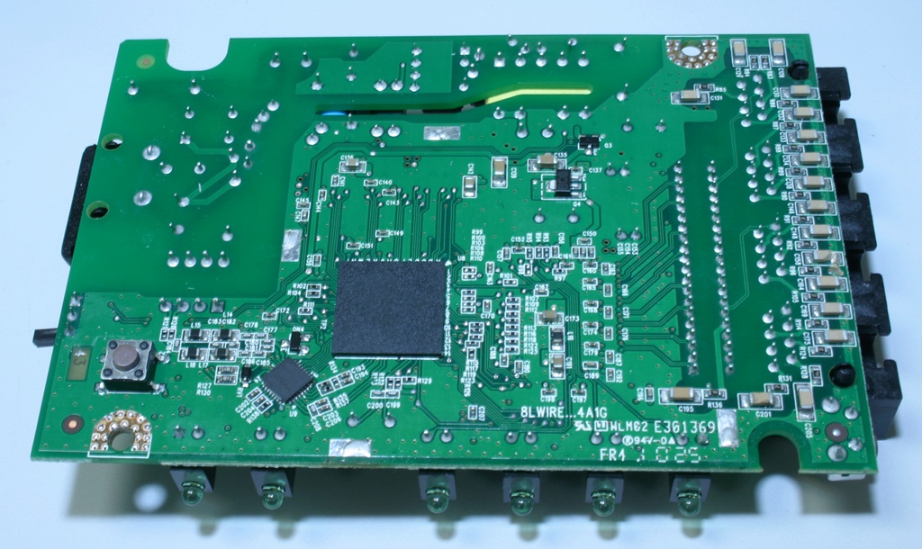
The Underside is Largely Unpopulated Except for the Powerline Chips
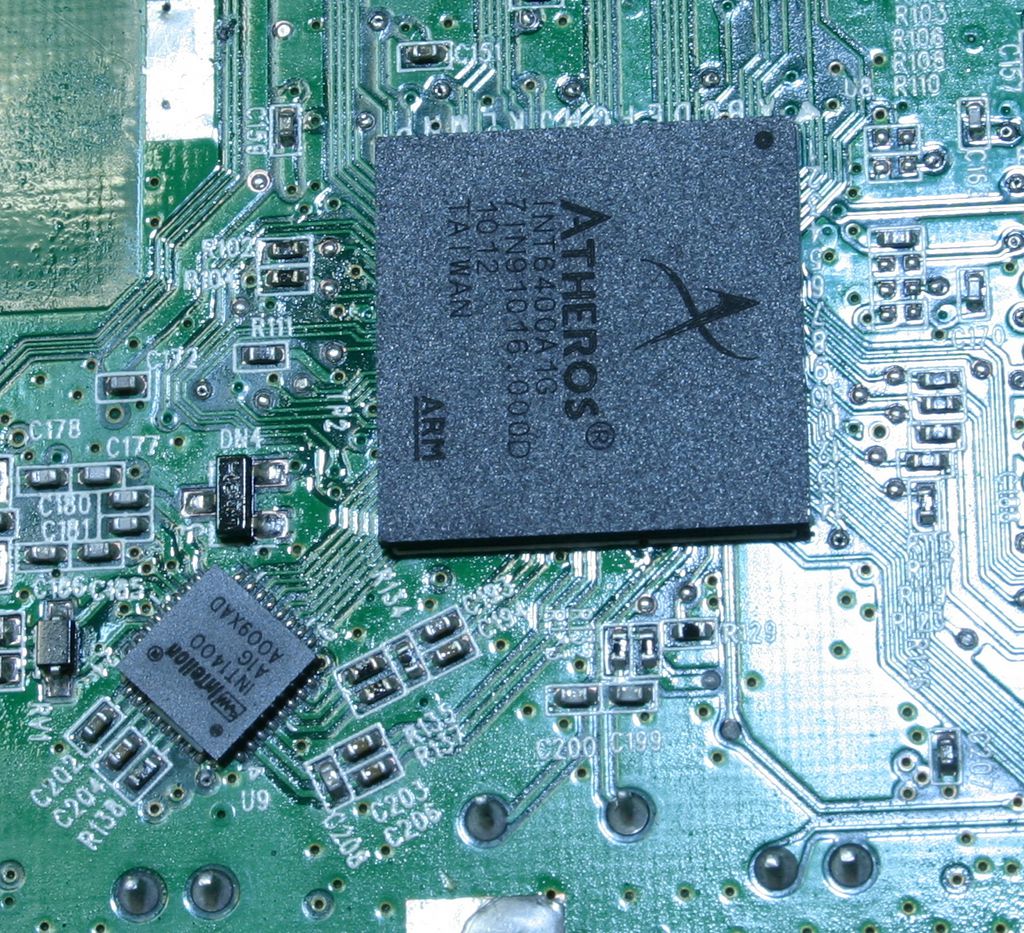
Up Close with the Powerline Chips
With a little bit of maneuvering, it is also possible to completely remove the PCB from the casing (as we have already done in this section's pictures). The top portion of the PCB shows a transformer, multiple capacitors and the Realtek RTL8306G 6 port Fast Ethernet switch controller. EtronTech supplies the DRAM for the chipset, and is the other big chip which can be seen in the photograph.
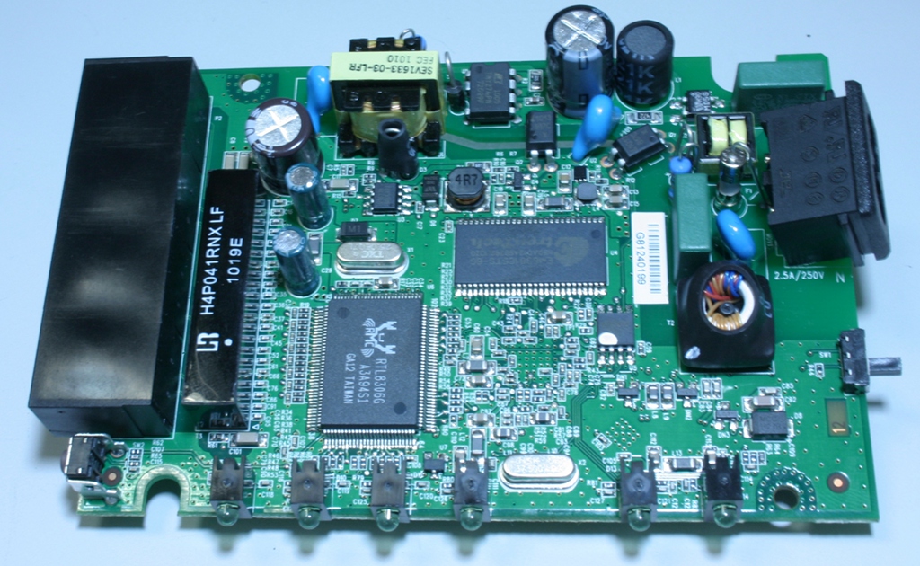
Top Side of the Board
So, we have taken a look at the internals of the WD Livewire. In the next section, we will look at how it performs.


31 Comments
View All Comments
jkostans - Tuesday, August 24, 2010 - link
Ethernet is not twisted to prevent radiation, it's to reduce noise in a differential transmission line. (The fact that ethernet signaling is differential reduces radiation and loss but not the twists) In theory by keeping the wires as close as possible any noise that influences one wire will equally influence the other wire in the same manner. When the subtraction is done to find the voltage, the net result of the noise will have no effect. It's like the equation (5+X) - (0+X) = 5. No matter what value of the noise (X) is, the equation will always equal 5.chromatix - Tuesday, August 24, 2010 - link
The twists have both effects, and effectively isolate the electromagnetic fields of the wires and their surroundings up to a certain frequency and down to a certain distance. It is the isolation which eliminates both emissions and received noise.flgt - Tuesday, August 24, 2010 - link
I think to some extent you're both right. The reduction in emissions comes from the fact that the signal is driven differentially (equal amplitude, opposite polarity) and the control of the electric fields which are generated. In a non-perfect transmission line there is a finite amount of cancellation between the two fields which can be improved with cable construction (Cat 6 > Cat 5 >> Romex). Twisting improves performance but a shield is required optimal emission performance. However the increased costs and installation time of shielded cables make them a less desirable solution as long as regulatory requirements can be met.As stated, differential signaling provides inherent common-mode noise immunity which is aided by the tight coupling of the twisted wires. The twisting helps ensure the radiated noise excites each conductor in the pair equally (again to some finite amount).
I don’t see this being a major issue for radio operators for a number of reasons:
1) The noise immunity provided by differential signaling allows the line to be driven at lower voltage levels, thereby further reducing emissions.
2) The use of OFDM allows each individual frequency channel to be operated at very low signal-to-noise ratios due to the low-order modulation scheme being used. This is the only way they can operate over such a horrible channel in the first place (your power line). They most likely operate each carrier at a very low signal level to make the composite spectrum look more like broadband noise. DSL essentially operates in the same way.
3) The signal will quickly attenuate since the channel is so bad.
Per Hansson - Wednesday, August 25, 2010 - link
I can confirm your suspicionsI recently bought the Belkin Gigabit Powerline HD networking kit
It managed to do 5Mbps over my powerlines, an apartement built 1990
When I turned on my FM radio there was an amazing ammount of noise in the reception when I was transmitting data, less so when I was not transmitting data but still some pops and cracks in the reception
When I unplugged the adapter the reception became perfect
Next test was to run the powerline adapter from the apartement out in to my garage, the speed now dropped to 1Mbps
To my suprise though it managed to even interfere with the FM reception in my car!
The signal got way harder to recieve, it did not crack and pop in the audio tho, but I think that may be simply due to the fact that the stereo in my car is much better at receiving a signal, and the fact that the car itself acts like a faraday cage...
To say the least I returned this "Gigabit" junk
yottabit - Tuesday, August 24, 2010 - link
There's a typo in the second sentence of the summary article on the anandtech home page... :(reckert - Tuesday, August 24, 2010 - link
In most homes, the electric coming in is 240v, and the circuits are split to 2 sets of 120v. I know from past experience power line protocols such as x10 couln't get their signals to jump between the two sides of the wiring without a special bridge.ganeshts - Tuesday, August 24, 2010 - link
reckert, as you mention, x10 needed something to plug in to bridge the legs of the circuits. However, as all Homeplug stuff is on high frequency, they bridge due to the capacitive effect of the bus bars in the circuit breakers. Therefore, you will not have a problem with the configuration you mention as long as you are using HomePlug certified devices.Souka - Tuesday, August 24, 2010 - link
My house build 1984...2 story, 2200 sq/ftCable modem on second floor, tv on 1st with BriteView media player.
Netgear XE-104 (up to 85Mbs claim)... on same curcuit directly plugged into wall I got barely 15Mbps. Different circuit in adjoining rooms 5Mbps. Different circuit on different floors...under 1Mbps and often dropped connection.
BELKIN F5D4073 (up to 85Mbps) Powerline Turbo similar results...
Also tried the kits in my parents 1960's 2 story 3500 sq'ft home....worse results...
I really like the idea of powerline tech, just doesn't deliver for me
ganeshts - Tuesday, August 24, 2010 - link
Souka,Please take a look at the SmallNetBuilder guide here, as it may be of some help to you: http://www.smallnetbuilder.com/lanwan/lanwan-basic...
It is best to buy these type of products from stores which have a good return policy / no restocking fee. Unless the consumer actually tries it out, it is not possible to know in advance as to how well the technology would work, as is evident in your case.
Souka - Tuesday, August 24, 2010 - link
I might give the XAVB5501 or XAVB5001 a shot when they come out....none of the listed retailers (or froogle.com) came up with any units available.I do wish they had dual ports... or at least in kits one of the units had dual ethernet ports.
Yes I can easily hook a switch to it, but rather not.