Everything You Always Wanted to Know About SDRAM (Memory): But Were Afraid to Ask
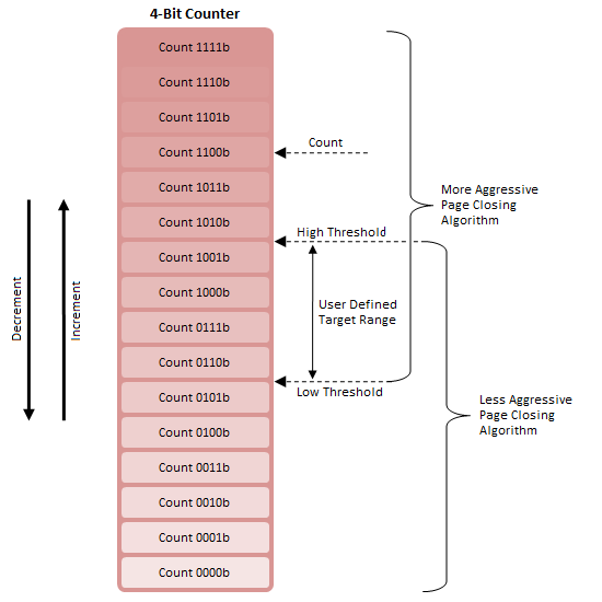
by Rajinder Gill on August 15, 2010 10:59 PM ESTFirst, consider a 4-bit counter with two adjustable thresholds (Figure 12). When Count is greater than High Threshold, Algorithm A is deemed appropriate; the same is true concerning Algorithm B and Count less than Low Threshold.
For the range between High Threshold and Low Threshold, either algorithm may be in effect. This is because a switch from Algorithm B to Algorithm A will occur only with Count greater than High Threshold and increasing and a switch from Algorithm A to Algorithm B will occur only with Count less than Low Threshold and decreasing.
The overlap range is also the Target Range as the system will naturally attempt to maintain Counter between these two points. This is true since Algorithm A tends to lower Count while Algorithm B tends to raise Count. This system acts to reduce or eliminate rapid thrashing between algorithms.
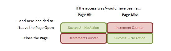
Next, define a truth table (Figure 13) defining how Count will vary. By doing so we can encode a feedback mechanism into our system. Successful predictions by the Adaptive Page Close Logic - a prevented page-miss access (good) in response to a decision to close a page or a facilitated page-hit access (good) in response to a decision to leave a page open - suggest no change to policy is required and so never modify Count.
For a facilitated page-miss access (bad) due to a poor decision to leave a page open, increment Count. If Count were to trend upward we could conceivably conclude that the current policy was most often wrong and not only that, tended to leave pages open far too long while "fishing" for page-hit operations. The current algorithm must not be closing pages aggressively enough.
For a prevented page-hit access (bad) due to a poor decision to close a page early, decrement Count. If Count were to trend downward we would suspect the opposite: the algorithm is too aggressively closing pages and leaving potential page-hits on the cutting room floor.
As best we can tell, this construct represent reality for APM Technology. Although we would like to believe the system has more than two gears (algorithms), our model perfectly explains the existing control register both in type and number.
Looking ahead you will see Max Page Close Limit and Min Page Close Limit are the specified High and Low Threshold values, respectively. Setting a larger difference increases the size of the feedback dead band, slowing the rate at which system responds to its own evaluative efforts. Mistake Counter is represented by the starting Count and should be set somewhere near the middle of the dead band.
Adaptive Timeout Counter sets the assertion time of any decision to keep a page open (i.e. how long before the decision to keep a page open stands before we give up hope of a page-hit access). Repeated access to the same page will reset this counter each time as long as the remaining lifetime is non-zero. Lower values result in a more aggressive page close policy and vice versa for higher values.
Request Rate, we believe, controls how often Count (Mistake Counter) is updated, and therefore how smoothly the system adapts to quickly changing workloads. There must be a good reason not to flippantly set this interrupt rate as low as possible. Perhaps this depletes hardware resources needed for other operations or maybe higher duty cycles disproportionally raises power consumption. Whatever the reason, there's more than a fair chance you can hurt performance if you're just spit-balling with this setting.


46 Comments
View All Comments
ekoostik - Tuesday, August 17, 2010 - link
Great article. Going to take me a few more reads. One question - why no mention of Command Rate (and I double checked the Memory Scaling on Core i7 article, absent there too)? CR is often included in RAM specs, e.g. 9-9-9-24-2T, but never fully discussed if mentioned at all. Is it just not important anymore?Muhammed - Tuesday, August 17, 2010 - link
Ok I managed to royally confuse my self !What I know is that DDR3 operates at 1/8 the rated frequency , that means in case of DDR3 @800MHz , the internal memory operations are actually running at 100MHz , but the memory is able to fetch 8-words every clock cycle .
So 100MHz X (8 words ) = 800 Word per second as data rate , then the manufacturer misleadingly label the RAM module as a 800MHz part .
so the real benefit of DDR3 over DDR or DDR2 comes not from increased operating frequency , but from higher bandwidth .
To stress that fact , I mention DDR2 @800MHz , it operates at 200Mhz (internal clock) , however it only fetches 4-words every clock cycle , (200X4 = 800 Words).
When DDR3 operates at 200MHz (internal operations) like DDR2 , it fetches double the data , effectively managing 1600 words per second .
NOW , in your article .. you mention the base clock (I/o Bus) and you mention the double data rate , I know the I/O Bus clock is always 2 or 4 times the internal clock , so DDR3 @ 100MHz , has a 400MHz I/O bus .. but I couldn't understand the I/O bus function and it's relation in data transmission and data rate .
I am missing something here , could you enlighten me ?
Edison5do - Tuesday, August 17, 2010 - link
I Really was Affraid..!!Edison5do - Tuesday, August 17, 2010 - link
Technical Reading !!! LOve Thishasherr - Wednesday, August 18, 2010 - link
Great article. But what i dont get is how the hell motherboard knows all those timings? In SPDs there are like N timings described, isnt there really more? At least in bios settings i see more.Another thing. I buy Kingston 1800 MT/s module, with SPDs up to 1333 MTs. I overclock and make it run @ rated 1800mt/s speed. All timings are on auto. How the hell mobo/bios guess all of them :)?
ClagMaster - Wednesday, August 18, 2010 - link
Afraid to Ask ?After perusing through this I find myself afraid to read.
Comprehensive article for a novice EE
just4U - Wednesday, August 18, 2010 - link
Great article and ..." ....should be to focus development on reducing absolute minimum latency requirements for timings such as CAS and tRCD, rather than chasing.."
I hope the memory makers and shakers out there read that!!
lyeoh - Saturday, August 21, 2010 - link
The mistake counter bit counts seem OK to me. In what way are they wrong?There are 9 MSB (most significant bits) in the table.
Yes there are 13 bits in the counter, but the 9 bits in the table only refer to the 9 "top bits" of those 13 bits.
For example, if I have an 8 bit counter but 4 bits in some table only refer to the 4 most significant bits, then that means that you'd only see all zeroes in those 4 bits when the counter has values from 0 to 15 (0x0 to 0xF). When the counter has values from 240 to 255 (0xF0 to 0xFF), you'd see all ones in those 4 bits.
As for the description, I don't know the details of how the stuff works, so I don't know whether it's wrong or not.
dia - Saturday, August 21, 2010 - link
Read the explanation here:http://download.intel.com/design/processor/datasht...
Page 79.
To quote:
"MISTAKECOUNTER.
This field is the upper 8 MSBs of a 12-bit counter. This counter adapts the
interval between assertions of the page close flag. For a less aggressive page
close, the length of the count interval is increased and vice versa for a more
aggressive page close policy."
Now look at the left hand column, it shows 8:0. That's 9 bits! It's a 13 bit counter.
If it were a 12 bit counter the maximum permissible selection value would be 4095 and not 8191.
datasegment - Saturday, August 21, 2010 - link
Quick fyi - 8k is not 8196, it is 8192 :)