Foxconn Black Ops - Raw, Unadulterated Power
by Rajinder Gill on July 30, 2008 11:00 PM EST- Posted in
- Motherboards
Board Layout and Features
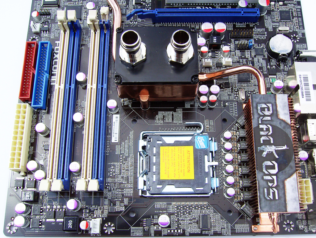 |
You won't find any multiple inductor based illusions to create the impression of more power phases on the Black Ops; what you see is pretty much what you get. Like DFI, Foxconn has opted to employ the use of the Volterra 1115MF PWM controller and accompanying Volterra MOSFETS in an 8-phase delivery configuration to supply processor power. The MOSFETS used here are almost double the size of the ones we are used to seeing on DFI's boards and are a lot more expensive. Foxconn tells us that peak current delivery potential is well in excess of 200A with a voltage rating of 2.5V. Simple math tells us this gives rise to the possibility of supplying 500W peak power, just to the CPU - overkill personified. [Ed: See, there actually is a use for those 1200W PSUs!]
Cooling of the Volterra MOSFETS is very crucial in getting anywhere near this current from them, and thankfully Foxconn uses a bolt-thru heatsink plus a backing plate to ensure that the heatsink remains in contact with all of the MOSFETS even if the socket bows under the pressure of LN2 pots or high torque cooler retention mechanisms. Looking at some of the 6GHz+ speeds that users have obtained using the Black Ops, this particular Volterra solution is certainly no slouch.
The processor socket is reasonably clean and allows for fairly easy insulation for the use of extreme cooling. The EPS12V connector is easy to access at the top left of the socket area. The CPU fan header is placed at the top of the board to the right of the CPU socket, and another five fan headers are placed in key locations on the board. All fan headers are fully speed controllable via the BIOS, providing ample flexibility for keeping the board cool in a variety of situations.
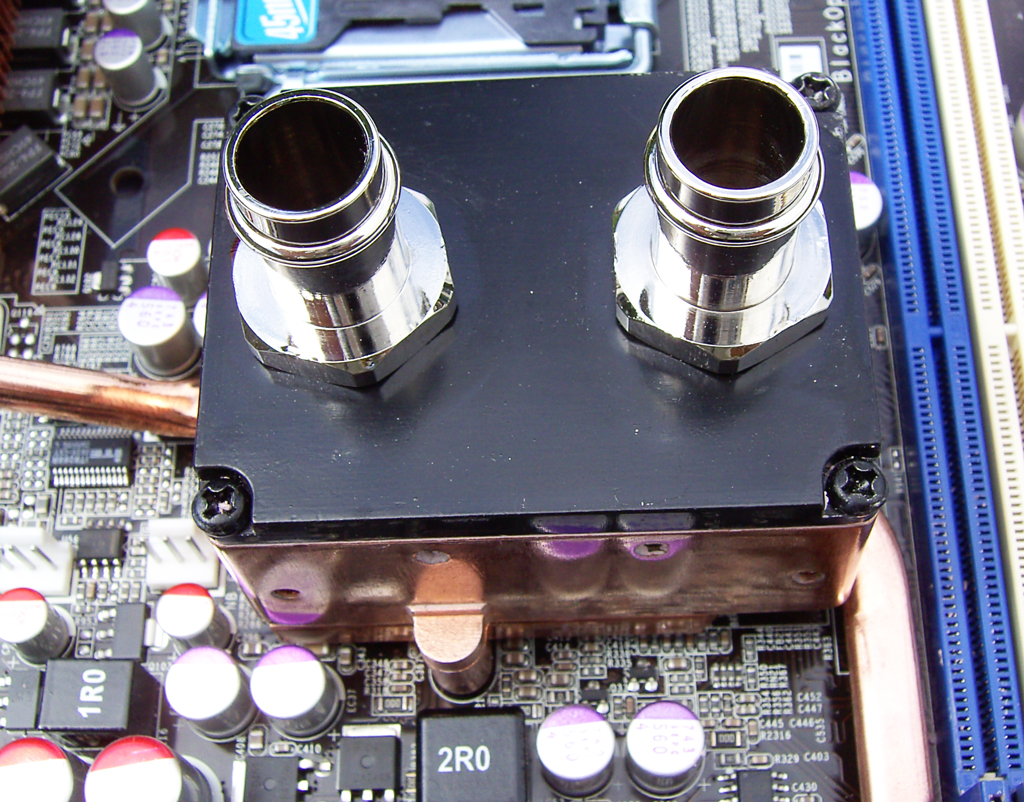 |
ASUS introduced boards with built-in water-cooling options last year. Foxconn continues with this trend but also provides users with a screw down plastic tube for dry ice or LN2 cooling of the Northbridge. (Note that additional motherboard insulation is still required.) The water-cooling top plate is anodized aluminum. Contrary to "popular belief", the chances of galvanic corrosion with this setup are miniscule and there should be no cause for concern. Galvanic corrosion can take years to manifest, and a suitable additive in some distilled de-ionized water should provide ample protection. Both 3/8" and 1/2" barbs are supplied, making it easy to connect the water block into an existing loop.
A small screw-down fan is also provided for users without access to water-cooling, although we feel that water-cooling really is necessary to get the most out of the X48. We ran overclock testing both using both air- and water-cooling and found that FSB scaling and board stability improved noticeably using water. Further, the whole board remains far cooler due to the heatpipe connecting the PWM and Southbridge heatsinks to the Northbridge, making for a more stable system overall - very effective indeed.
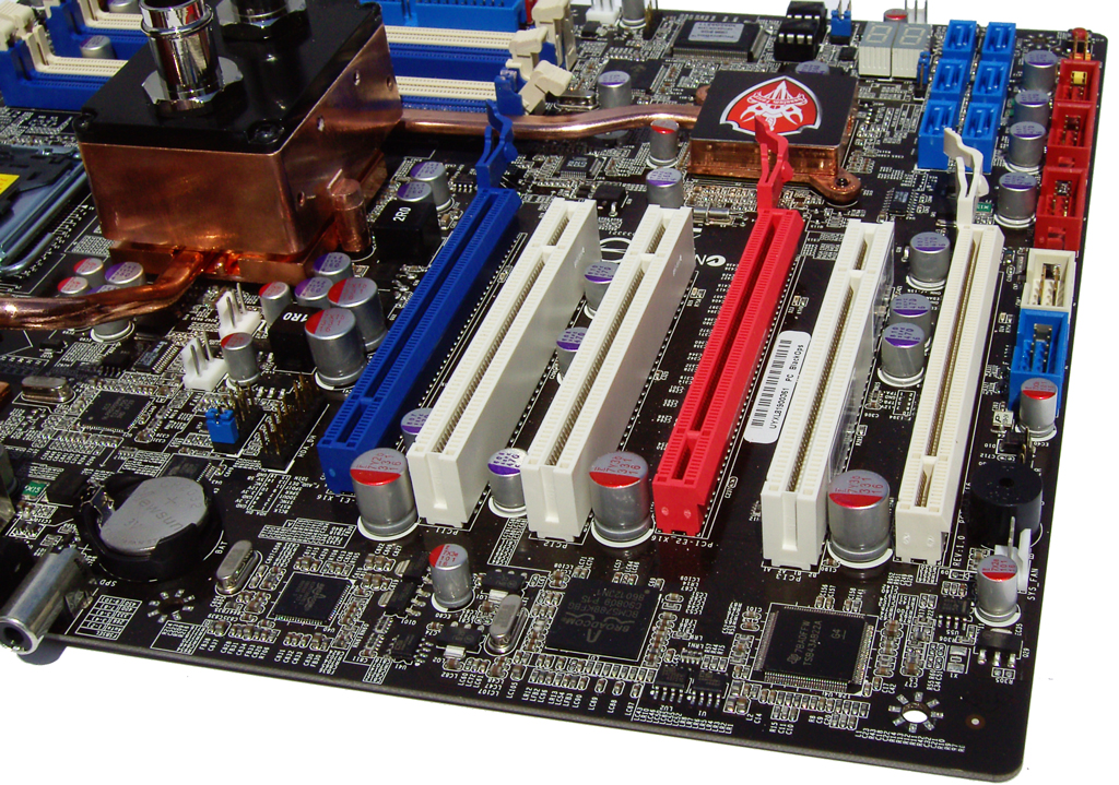 |
Three mechanical x16 length PCI-E slots (2x16 + 1x4 electrical) and three PCI slots make up the expansion of the Black Ops. If using CrossFire with dual-slot GPUs, two of the PCI slots will be inaccessible while the middle PCI slot might just have enough room to house a slim soundcard. Using a long GPU card with a dual-slot cooler will also block three of the SATA ports, although the remaining three should be more than enough for most benchmarking runs.
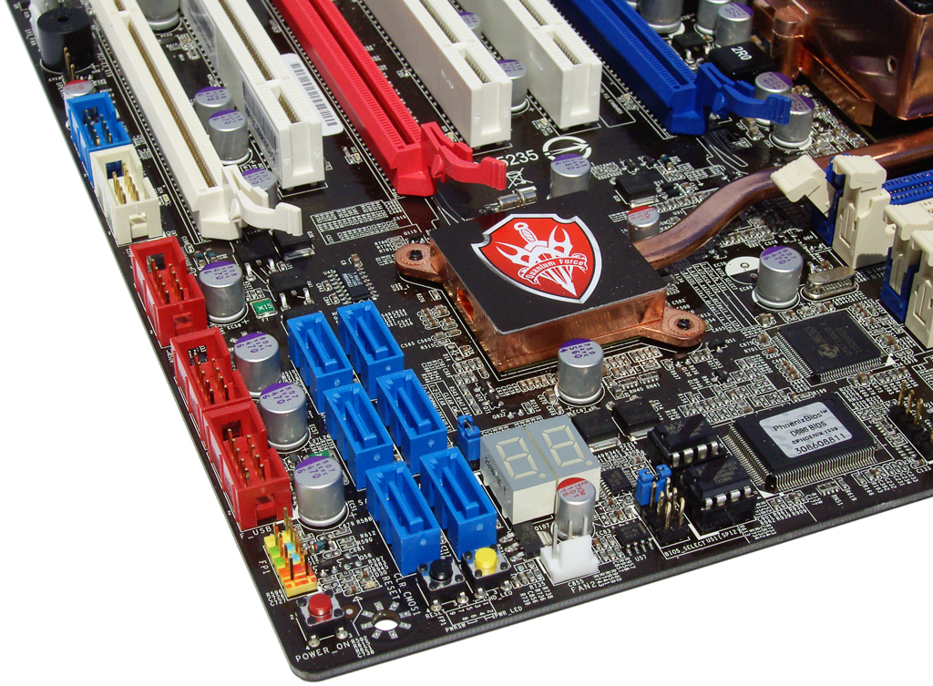 |
Six SATA ports are lined up in banks of three horizontally in the bottom right corner of the board. As we stated above, three will be blocked by the use of a long GPU card in the red PCI-E slot. Power/reset and CMOS clear pushbutton switches are situated at the edge of the board along with a post code display for debugging. A welcome change is the presence of two socket loaded 8-pin EPROMs for BIOS storage. Each chip can store a different BIOS version, which is selectable via an onboard jumper. We quite like the idea of this, as it means you can store your favorite benchmarking and stable BIOS releases and switch between them with a minimal amount of fuss. Three internal USB connectors sit below the SATA ports with the COM and internal 1394 connectors situated underneath the last PCI slot.
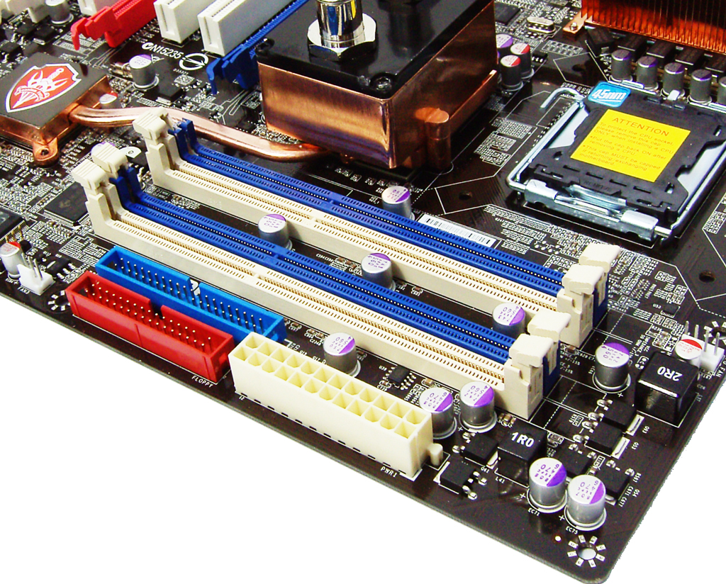 |
The presence of a single inductor on the output side of the VDimm circuit suggests that Foxconn opted for a 2-FET single-phase power solution to provide memory power. Slot placement leaves room to insert longer graphics cards in the primary PEG slot with just enough clearance to use a Corsair Dominator fan to cool memory modules. The ATX 12V connector sits to the right of the memory slots together with the IDE and floppy drive connectors.
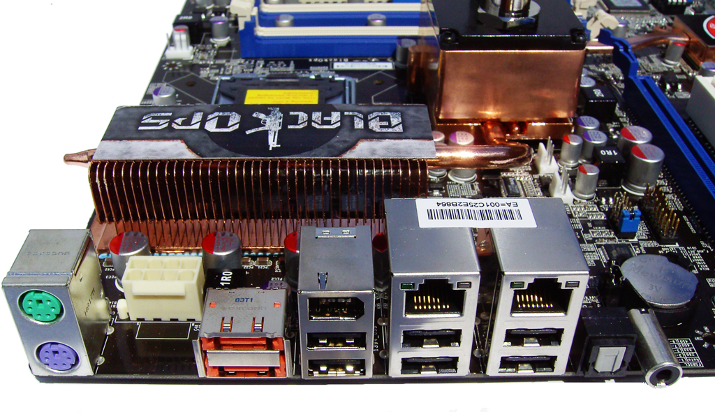 |
The rear I/O panel is home to PS/2 Keyboard and mouse ports, two eSATA connectors, two RJ45 Gigabit Ethernet ports, an IEEE-1394a port, and six USB ports.


32 Comments
View All Comments
elfguy - Thursday, July 31, 2008 - link
I disagree. A company that gets called on a screwed up practice, and gets tons of bad press, will always try to justify itself and if they see potential profit loss, they will say whatever they can to calm things down. We still don't know for sure if it was intentional or not, we only have their word for it.If they had not been called on it, things would have stayed broken. Many companies do screwed up things, and the best thing we can do is show them that look, you go against your customers needs, and you will suffer for it, in the only way they care about, that is loss sales. So I say support your alternative OSes, boycott Foxconn.
AmberClad - Thursday, July 31, 2008 - link
Good luck on trying to boycott Foxconn. The vast majority of their business is not in retail motherboards -- it's in the manufacturing of game consoles, cell phones, and various electronic components. Any motherboard you buy from another manufacturer is more than likely going to have some Foxconn components in them.