Overclocking Intel's New 45nm QX9650: The Rules Have Changed
by Kris Boughton on December 19, 2007 2:00 AM EST- Posted in
- CPUs
Overclock That CPU
With the memory and memory subsystems out of the way, we are finally ready to see what the processor can do. Because we have already decided on our target FSB we must accept for the time being that our final CPU frequencies will be limited to discrete steeps equal to our FSB. This is by design and affords us the knowledge that any Prime95 errors met during our last testing phase come from the CPU and nothing else. As always, varying the processor's multiplier changes only the CPU frequency - if memory is stable at 8 x 400 then by definition it's also stable at 9 x 400. Assuming we have decided to run 1:1, in both cases, the memory continues to operate at DDR-800 regardless of CPU speed. Later you can tune your final clocks by adjusting the FSB if you so choose.
 All green means everything is good. Remember to give the program time to run |
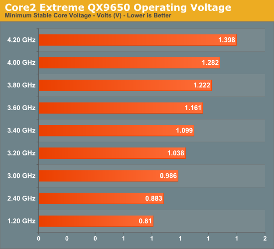
Once again, enter your motherboard's BIOS, this time adjusting only the CPU multiplier and the CPU voltage to set a potential overclocking frequency. Using custom water-cooling we were able to scale our QX9650 as shown below. Please note that all processors are different and voltage response curves generated using one CPU are not directly applicable to another. Your processor may perform slightly better or worse and these illustrations are only a general guideline. (The values shown are full-load CPU supply voltages and not the VID settings that we had to set.)
After booting to the Windows desktop, fire up Prime95 once again, this time choosing the option to run small FFTs as this setting places maximum stress on your CPU and leads to the highest load temperatures. As before, run at least 30 minutes while watching for errors. There are a few different potential failure modes, the least severe being a rounding error which causes one or more of the calculation threads to quit, changing the child window icon from green to red. Normally, with 45nm processors this is a good indication of a memory error, but since we know the memory is stable we can safely blame the CPU. In this case, the corrective action is to increase the CPU VID by a single step and try again. If the system freezes or freezes and then quickly resets, you will need to increase the CPU voltage by more than a single-step increment. Save yourself the hassle of multiple failures, increase CPU voltage by 0.05V or more, and try again. Later, back this down if possible until the CPU is just above the minimum required Vcore.
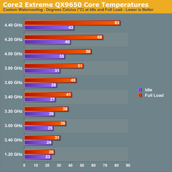
Depending on the cooling in use, you may find your overclock temperature limited. The QX9650 has a maximum thermal specification of 64.5°C but can generally handle temperatures as high as about 70°C before heat becomes a significant factor in scaling. Besides the core temperatures, the voltage regulator module (VRM) supply current can also function as a limiting factor. We saw before just how much current, in amps, the VRM circuit must provide under CPU full-load conditions in order to maintain stability. Current in excess of about 160A can be quite straining for even high-performance motherboards - make sure you adequately cool this area with at least a single, low-speed 120mm or larger fan if you plan to push a board this hard.
One of the great new features of the 45nm Core 2 family of processors is the ability to make use of non-integer multipliers. Sometimes referred to as half-multipliers, these values allow you to step your CPU frequency in increments one-half that of your FSB. Overclockers intent on running 400MHz FSB can now use a 10.5x multiplier to set a final CPU frequency of 4.2GHz, up from 4.0GHz (when 4.4GHz may be unachievable) without even touching the FSB. Consider this potential advantage if your motherboard allows use of these settings.
After some time experimenting with what works and what does not, you should start to get a feel for how your system responds to changes. During this time you should also learn how your CPU scales with voltage and exactly what speeds and timings to use with your memory subsystem. This three-phase approach helps lay the groundwork for the development of key overclocking skills and provides those new to overclocking with some ideas on how to approach the subject. Only once you understand the theory behind this basic methodology can you begin to safely stray into uncharted territory.


56 Comments
View All Comments
Lifted - Wednesday, December 19, 2007 - link
Very impressive. Seems more like a thesis paper than a typical tech site article. While the content on AT is of a higher quality than the rest of the sites out there, I think the other authors, founder included, could learn a thing or two from an article like this. Less commentary/controversy and more quality is the way to go.AssBall - Wednesday, December 19, 2007 - link
Shouldn't page 3's title be "Exlporing the limits of 45nm Halfnium"? :Dhttp://www.webelements.com/webelements/elements/te...">http://www.webelements.com/webelements/elements/te...
lifeguard1999 - Wednesday, December 19, 2007 - link
"Do they worry more about the $5000-$10000 per month (or more) spent on the employee using a workstation, or the $10-$30 spent on the power for the workstation? The greater concern is often whether or not a given location has the capacity to power the workstations, not how much the power will cost."For High Performance Computers (HPC a.k.a. supercomputers) every little bit helps. We are not only concerned about the power from the CPU, but also the power from the little 5 Watt Ethernet port that goes unused, but consumes power. When you are talking about HPC systems, they now scale into the tens-of-thousands of CPUs. That 5 Watt Ethernet port is now a 50 KWatt problem just from the additional power required. That Problem now has to be cooled as well. More cooling requires more power. Now can your infrastructure handle the power and cooling load, or does it need to be upgraded?
This is somewhat of a straw-man argument since most (but not all) HPC vendors know about the problem. Most HPC vendors do not include items on their systems that are not used. They know that if they want to stay in the race with their competitors that they have to meet or exceed performance benchmarks. Those performance benchmarks not only include how fast it can execute software, but also how much power and cooling and (can you guess it?) noise.
In 2005, we started looking at what it would take to house our 2009 HPC system. In 2007, we started upgrades to be able to handle the power and cooling needed. The local power company loves us, even though they have to increase their power substation.
Thought for the day:
How many car batteries does it take to make a UPS for a HPC system with tens-of-thousands of CPUs?
CobraT1 - Wednesday, December 19, 2007 - link
"Thought for the day:How many car batteries does it take to make a UPS for a HPC system with tens-of-thousands of CPUs?"
0.
Car batteries are not used in neither static nor rotary UPS's.
tronicson - Wednesday, December 19, 2007 - link
this is a great article - very technical, will have to read it step by step to get it all ;-)but i have one question that remains for me.. how is it about electromigration with the very filigran 45nm structures? we have here new materials like the hafnium based high-k dielectricum, guess this may improove the resistance agains em... but how far may we really push this cpu until we risk very short life and destruction? intel gives a headroom until max 1.3625V .. well what can i risk to give with a good waterchill? how far can i go?
i mean feeding a 45nm core p.ex. 1,5V is the same as giving a 65nm 1,6375! would you do that to your Q6600?
eilersr - Wednesday, December 19, 2007 - link
Electromigration is an effect usually seen in the interconnect, not in the gate stack. It occurs when a wire (or material) has a high enough current density that the atoms actually move, leading to an open circuit, or in some cases, a short.To address your questions:
1. The high-k dielectric in the gate stack has no effect on the resistance of the interconnect
2. The finer features of wires on a 45nm process do have a lower threshold to electromigration effects, ie smaller wires have a lower current density they can tolerate before breaking.
3. The effects of electromigration are fairly well understood at this point, there are all kinds of automated checks built in to the design tools before tapeout as well as very robust reliability tests performed on the chips prior to volume production to catch these types of reliability issues.
4. The voltage a chip can tolerate is limited by a number of factors. Ignoring breakdown voltages and other effects limited by the physics of transistor operation, heat is where most OC'ers are concerned. As power dissipation is most crudely though of in terms of CVf^2 (capacitance times voltage times frequency-squared), the reduced capacitance in the gate due to the high-k dielectric does dramatically lower power power dissipation, and is well cited. The other main component in modern CPU's is the leakage, which again is helped by the high-k dielectric. So you should expect to be able to hit a bit higher voltage before hitting a thermal envelope limitation. However, the actual voltage it can tolerate is going to depend on the CPU and what corner of the process it came from. In all, there's no general guideline for what is "safe". Of course, anything over the recommended isn't "safe", but the only way you'll find out, unfortunately, is trial and error.
eilersr - Wednesday, December 19, 2007 - link
Doh! Just noticed my own mistake:high-k dielectric does not reduce capacitance! Quite the contrary, a high-k dielectric will have higher capacitance if the thickness is kept constant. Don't know what I was thinking.
Regardless, the capacitance of the gate stack is a factor, as the article mentioned. I don't know how the cap of Intel's 45nm gate compares with that of their 65nm gate, but I would venture it is lower:
1. The area of the FET's is smaller, so less W*L parallel plate cap.
2. The thickness of the dielectric was increased. Usually this decreases cap, but the addition of high-k counter acts that. Hard to say what balance was actually achieved.
This is just a guess, only the process engineers no for sure :)
kjboughton - Wednesday, December 19, 2007 - link
Asking how much voltage can be safetly applied to a (45nm) CPU is a lot like asking which story of a building can you jump from without the risk of breaking both legs on the landing. There's inherent risk in exceeding the manufacturer's specification at all and if you asked Intel what they thought I know exactly what they would say -- 1.3625V (or whatever the maximum rated VID value is). The fact of the matter is that choices like these can only be made by you. Personally, I feel exceeding about 1.4V with a quad 45nm CPU is a lot like beating your head against a wall, especially if your main concern is stability. My recommendation is that you stay below this value, assuming you have adequate cooling and can keep your core temperatures in check.renard01 - Wednesday, December 19, 2007 - link
I just wanted to tell you that I am impressed by your article! Deep and practical at the same time.Go on like this.
This is an impressive CPU!!
regards,
Alexander
defter - Wednesday, December 19, 2007 - link
People stop posting silly comments like: "Intel's TDP is below real power consumption, it isn't comparable to AMD's TDP".Here we have a 130W TDP CPU consuming 54W under load.