ASUS Maximus Extreme - the Extreme Benchmarker's Choice?
by Rajinder Gill on December 10, 2007 8:00 AM EST- Posted in
- Motherboards
ASUS Maximus Extreme Board Layout and Features
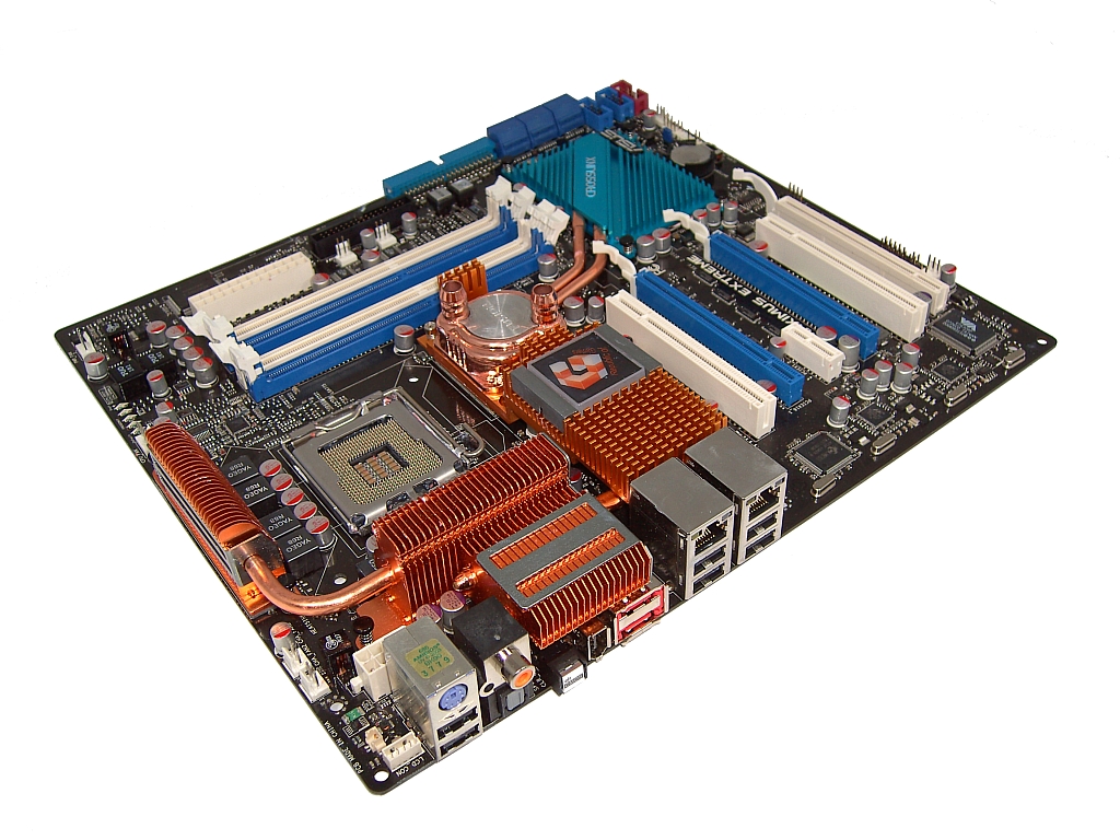 |
ASUS has extended the width of this board slightly past standard ATX measurements to allow for better overall DIMM socket placement. Note the close proximity of the DIMM slots to the Northbridge, allowing for better signal transfer potential at high DDR3 speeds. For those using smaller non-tower PC cases, the additional width over conventional ATX boards is around 4cm. This is worth keeping in mind if space is already an issue.
Eight well-placed fan headers are available at key areas of the board with a decent level of control via the BIOS or ASUS' AI software suite. We also find ASUS' Volt Minder LED system for the CPU, Northbridge, and Southbridge areas. As this board is ASUS' current flagship product, we also find a wired LCD diagnostic poster and additional items like the LED lit ROG logo on the Northbridge heatsink. The OPT fan headers are also controllable, by use of the supplied thermal probes, which can be attached to areas of the board at the users discretion.
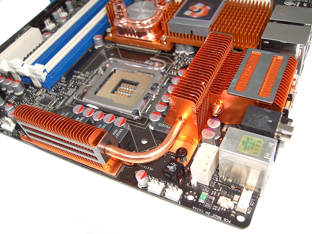 |
The EPS 12V connector is near the CPU socket area. An internal S/PDIF pin-out and the connector for the LCD poster is located at the top left hand corner of the board (lower right of the picture). CPU voltage comes via the 8-phase ADP 3228 PWM controller (4 MOSFETs per phase for a total of 32 MOSFETs). The PWM cooling heatsink is large enough to dissipate heat under high Vcore and heavy processor loading; however, the central MOSFETs do not have good heatsink contact as the board bows slightly under the pressure of a CPU cooler, pulling the central MOSFETs away from the sink. If you plan to push high levels of Vcore, it may be prudent to use additional non-conductive thermal paste over the central MOSFETs to ensure heat transfer. Again, ASUS has chosen to use a hybrid heatsink/water block combination for the Northbridge cooling solution. We approached this combo with a little trepidation after our experience with water-cooling the NB on the Maximus Formula last month.
This time, we used screw fitting hose clamps, rather than the supplied spring clamps to ensure that our 1/2" tubing would not work loose during testing. ASUS has assured us that ROG boards will be shipping with screw-type hose fittings in the future. We also removed the entire heatsink assembly to check for contact between the heatsink and Northbridge HIS (Integrated Heat Spreader). The thermal pads ASUS uses form a very secure bond to the Northbridge at ambient temperatures; as a result, we had to use a hair dryer to heat the board plus 40 degrees to work the block loose. We advise users not to force the heatsink assembly away from the board. We have seen examples of Northbridge chips pulled off boards by over-zealous users - a quick way to kill a board without a chance for an RMA if a problem arises in the future.
IHS to heatsink contact was a lot better on this board than our first Maximus Formula sample (something later fixed in shipping boards). We still decided it best to remove the stock cooling pad with an acetone based cleaner and use a good thermal paste instead, as the paste has a lower thermal resistance than thermal pads allowing for better thermal transfer. A combination of air- and water-cooling for the Northbridge brings the best results. The X38 chipset does seem to be heat sensitive; temperatures in excess of 45-50C can cause system instability.
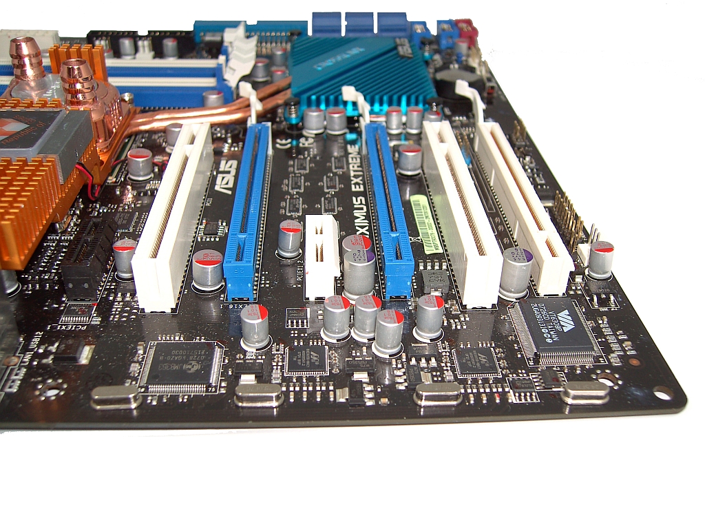 |
Any board that uses the x38 chipset is bound to have 2 X PCI-E 2.0 slots. ASUS has gone a step further and used a bridge chip to allow a third PCI-E 1.1 slot running at x8 speed. The exciting upshot for users is the potential to run Tri-Fire (future drivers permitting), albeit with the PCI-E slots running in 16x-16x-8x mode. The obvious side effect is this configuration leaves little room between the PCI-E slots. Users who wish to use full-coverage water blocks to cool their graphics cards will need to either modify their PC cases or use GPU-only water blocks.
The top PCI-E x1 slot is for the supplied SupremeFX II soundcard, featuring the ADI 1988B 8-channel High Definition Audio CODEC. Two PCI slots are available, though in the case of using dual graphics cards the top PCI slot is the only port that may be used. Finally, an onboard USB connector is located above the lowest PCI-E port.
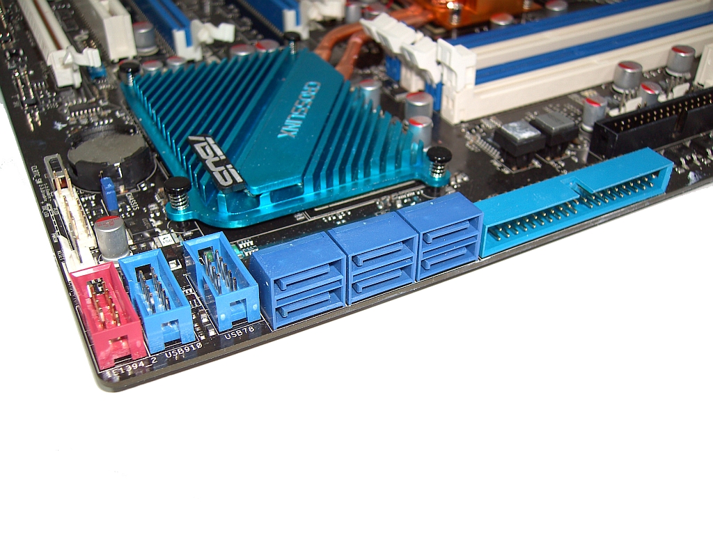 |
The Intel ICH9R Southbridge provides us with six SATA ports. Below the ports, we find two USB connectors and an IEEE 1394a port. The IDE connector sits above the SATA connectors, remaining accessible even when using long graphic cards in the top PEG slot.
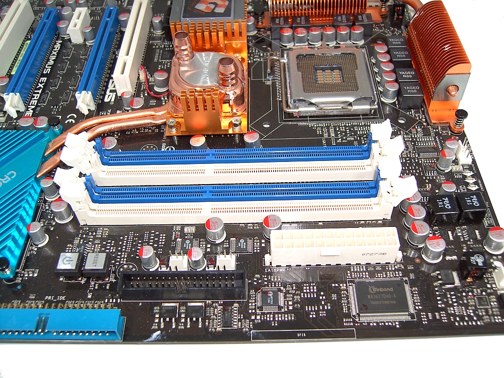 |
We have four (almost) centrally placed DIMM slots for memory, offering full support for 8GB. ASUS uses this memory slot layout to minimize the potential of inductance and signal crosstalk, a wise decision based upon the potential speed that DDR3 brings to the table. The floppy drive connector sits just in front of the DIMM slots. To the right of this we have the 24-pin ATX 12V connector. As mentioned earlier, the added width of this motherboard ensures plenty of room around all peripheral connectors on the right side of the board. The power and reset switches are just behind the IDE connector, keeping them exposed for use even when multiple graphics cards are present.
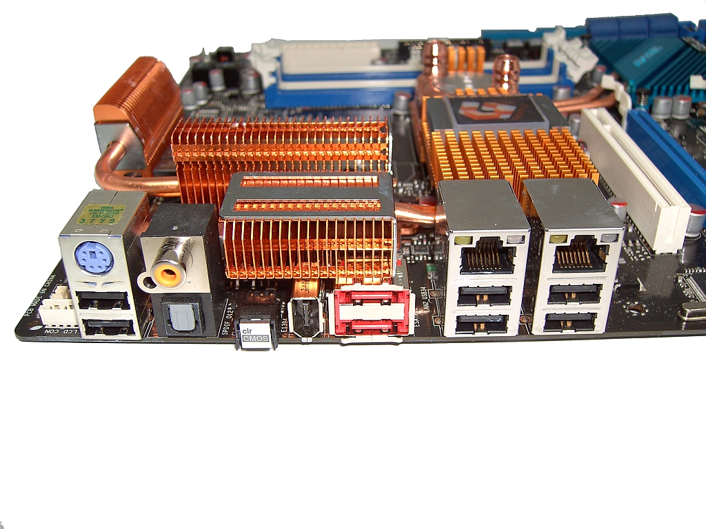 |
The rear IO panel features a PS/2 keyboard port with two USB slots directly underneath; users with a PS/2 mouse will need a PS/2 to USB adaptor. A Coaxial S/PDIF output is also present, together with a TOSLINK output. To the right we have the Clear CMOS button, making it easy to clear the CMOS even after installing the board in a case. There is a rear FireWire port, dual Gigabit LAN (featuring teaming support), and four additional USB ports. In addition, ASUS also provides two e-SATA ports on the rear IO plate.


27 Comments
View All Comments
retrospooty - Monday, December 10, 2007 - link
Wireless works yes. They are linked up through the base and work in dos mode. Both RF, and bluetooth meese work.kilkennycat - Monday, December 10, 2007 - link
I notice from the board picture that the rear mounting holes are still in the corners of the board, so if the WIDTH is 4cm more than the standard ATX, does the board need special mounting ? I assume that WIDTH means the distance across the edge of the board in contact with the rear of the case. Please correct if my assumption is wrong.Rajinder Gill - Monday, December 10, 2007 - link
THe width is the length across the top edge of the board. Screw hole spacing is still standard ATX, just that this board over-hangs by a few cm (the Sata port end will protrude further into your case) ...regards
Raja
kilkennycat - Monday, December 10, 2007 - link
As yes, you actually mean DEPTH of course, if referencing tower case dimensions (Height x Width x Depth). So any case wishing to accommodate this board needs to have at least 4cm DEEPER front to rear clearance for the motherboard, nothing to do with it being a mid-tower or full-tower. Am I right?Might also preclude using this MB in those cases having the motherboard mounted on a slide-in ATX tray ( a great feature, btw ), as they may have a lip or other registration hardware on the leading-edge of the tray.
retrospooty - Monday, December 10, 2007 - link
What size are they? I cant find it here, or on Asus's site. They look like 1/4 inch - which kind of sucks.Rajinder Gill - Monday, December 10, 2007 - link
The fittings are 1/4", but ASUS does provide adapetrs to use 1/2 tubing..Raja..
retrospooty - Monday, December 10, 2007 - link
thanks... bummer. 1/4 restricts my flow.