ASUS Maximus Extreme - the Extreme Benchmarker's Choice?
by Rajinder Gill on December 10, 2007 8:00 AM EST- Posted in
- Motherboards
BIOS, Continued
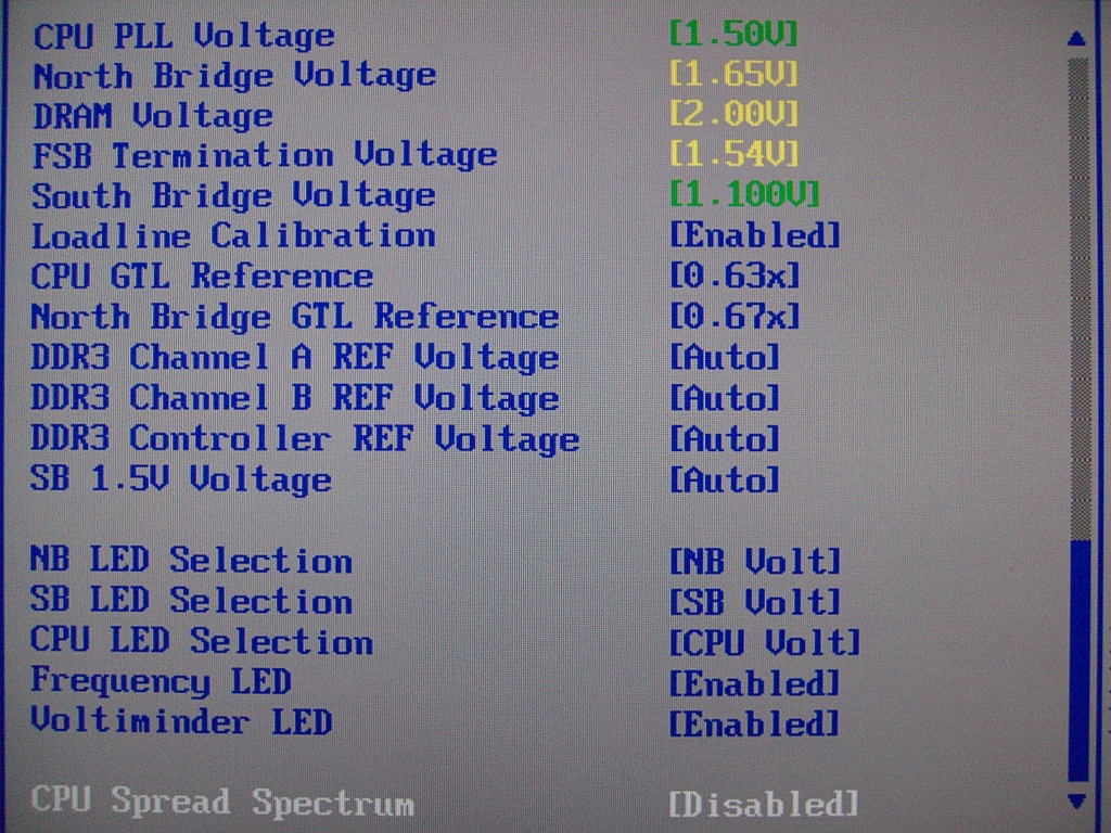 |
CPU PLL Voltage: Scale range is 1.5-3V in 0.02V increments. Stock is 1.5V, and although overvolting can bring increases to FSB limits, we do not recommend using past 1.75V for long-term use.
North Bridge Voltage: Scale range is 1.25V-2.05v. NB temperatures greatly affect stability, and temps over 47C are prone to failures during longer Prime torture test runs. We recommend active cooling of the NB for overclocking. A combination of air- and water-cooling generates the best results when using the stock ASUS water block and heatsink combo. Voltages around 1.61V-1.65V are required for overclocking past 440FSB.
DRAM Voltage: ASUS provides us with a 1.5V-3.04V scale. The 0803 BIOS does overvolt by around 0.05V, and users are advised to subtract this value from the BIOS setting to stay within warranty voltages for memory. (Yes, we said that with a straight face!)
FSB Termination Voltage: Voltage scale runs from 1.2V-2V. Quad-core CPU overclocking is especially dependent upon VTT and GTL voltage ratios. We found a setting of 1.54V to be a sweet spot on our board for speeds over 440FSB.
Loadline Calibration: Available options are Auto, Disabled, and Enabled. Use "Enabled" for overclocking. This function reduces Vcore voltage sag. With Loadline Calibration "Enabled", we measured a load droop of around 0.02V using the 0803 BIOS.
CPU GTL Reference: This setting is a derivative or ratio of the applied VTT voltage. A setting of 0.63x provides the most headroom for overclocking quad-core processors.
Northbridge GTL Reference: A value of 67% generally provides the best level of stability on this motherboard.
DDR3 Controller REF Voltage: This setting works off a principal percentage of DRAM voltage - 50%. Altering either Channel A or B values away from DDR3_REF generally creates instability issues. There may however be gains in applying an overvolt to DDR3 Controller REF Voltage if attempting to reach high FSB/memory speeds.
450FSB Stability Test and BIOS settings
In order to provide users with a starting point for a decent overclock we provide our BIOS settings, together with a 4-hour pass of OCCT @ 8x450FSB with our QX6800 processor.
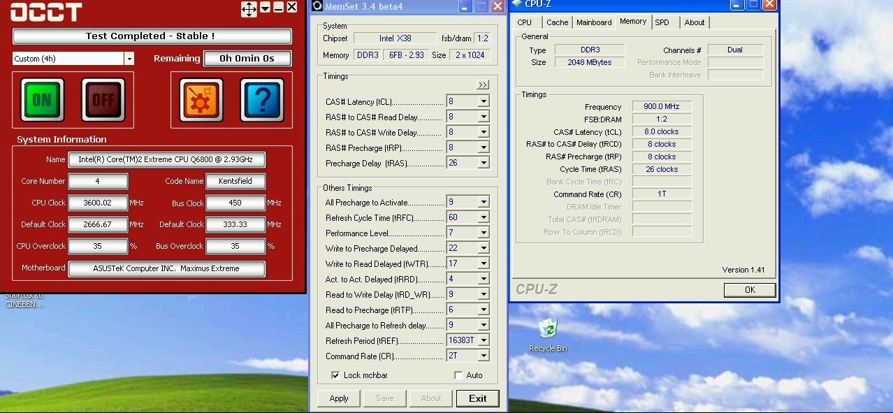 |
| 450FSB Quad-Core BIOS Settings | |
| CPU Settings | |
| CPU Feature Ai Overclock Tuner | [Manual] |
| OC From CPU Level Up | [Auto] |
| OC From Memory Level Up | [Auto] |
| CPU Ratio Setting | [8.0] |
| FSB Frequency | [450] |
| FSB Strap to North Bridge | [333MHz] |
| PCI/E Frequency | [110] |
| DRAM Settings | |
| DRAM Frequency | [DDR3-1801MHz] |
| DRAM Command Rate | [1T] |
| DRAM Timing Control | [Manual] |
| CAS# Latency | [8] |
| RAS# to CAS Delay | [8] |
| RAS# Precharge | [8] |
| RAS# Active Time | [26] |
| RAS# To Ras# Delay | [4] |
| Row Refresh Cycle Time | [60] |
| Write Recovery Time | [9] |
| Read To Precharge Time | [6] |
| Read To Write Delay(S/D) | [9] |
| Write To Read Delay(S) | [5] |
| Write To Read Delay(D) | [6] |
| Read To Read Delay(S) | [4] |
| Read To Read Delay(D) | [7] |
| Write To Write Delay(S) | [4] |
| Write To Write Delay(D) | [7] |
| DRAM Static Read Control | [Disabled] |
| Dram Dynamic Write Control | [Disabled] |
| Ai Clock Twister | [Strong] |
| Transaction Booster | [Enabled] |
| Boost Level | [2] |
| Voltage Settings | |
| CPU Voltage | [1.43125v] |
| CPU PLL Voltage | [1.5V] |
| North Bridge Voltage | [1.61v] |
| DRAM Voltage | [2.06v] |
| FSB Termination Voltage | [1.54v] |
| South Bridge Voltage | [Auto] |
| Loadline Calibration | [Enabled] |
| CPU GTL Reference | [0.63x] |
| North Bridge GTL Reference | [0.67x] |
| DDR2 Channel A REF Voltage | [Auto] |
| DDR2 Channel B REF Voltage | [Auto] |
| DDR2 Controller REF Voltage | [DDR2_REF] |
| SB 1.5V Voltage | [Auto] |


27 Comments
View All Comments
retrospooty - Monday, December 10, 2007 - link
Wireless works yes. They are linked up through the base and work in dos mode. Both RF, and bluetooth meese work.kilkennycat - Monday, December 10, 2007 - link
I notice from the board picture that the rear mounting holes are still in the corners of the board, so if the WIDTH is 4cm more than the standard ATX, does the board need special mounting ? I assume that WIDTH means the distance across the edge of the board in contact with the rear of the case. Please correct if my assumption is wrong.Rajinder Gill - Monday, December 10, 2007 - link
THe width is the length across the top edge of the board. Screw hole spacing is still standard ATX, just that this board over-hangs by a few cm (the Sata port end will protrude further into your case) ...regards
Raja
kilkennycat - Monday, December 10, 2007 - link
As yes, you actually mean DEPTH of course, if referencing tower case dimensions (Height x Width x Depth). So any case wishing to accommodate this board needs to have at least 4cm DEEPER front to rear clearance for the motherboard, nothing to do with it being a mid-tower or full-tower. Am I right?Might also preclude using this MB in those cases having the motherboard mounted on a slide-in ATX tray ( a great feature, btw ), as they may have a lip or other registration hardware on the leading-edge of the tray.
retrospooty - Monday, December 10, 2007 - link
What size are they? I cant find it here, or on Asus's site. They look like 1/4 inch - which kind of sucks.Rajinder Gill - Monday, December 10, 2007 - link
The fittings are 1/4", but ASUS does provide adapetrs to use 1/2 tubing..Raja..
retrospooty - Monday, December 10, 2007 - link
thanks... bummer. 1/4 restricts my flow.