The Single 12V Rail SilverStone Olympia OP650
by Christoph Katzer on July 13, 2007 12:00 PM EST- Posted in
- Cases/Cooling/PSUs
The Inside
After opening the housing we are presented with a very clean and systematic arrangement of components. Firstly, the two big heatsinks reveal the first signs of the old Etasis crew. In the most recent designs from Etasis, we find power supplies built with two printed circuit boards that still fit into a standard sized housing. This was made possible through the selection of components which are very short.
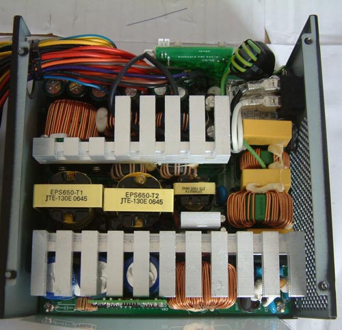
The same is clearly visible on first sight in our Silverstone Olympia power supply. Where other manufacturers are using a big capacitor on the primary section, Silverstone designed their PSU using three smaller ones to fit under the massive heatsink. The second difference to most other power supplies is that there are three transformers in the middle of the PCB. Normally this is implemented with one big transformer used to generate all outputs to the PC and a smaller transformer to generate the 5v stand-by rail.
Filtering stage
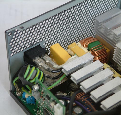
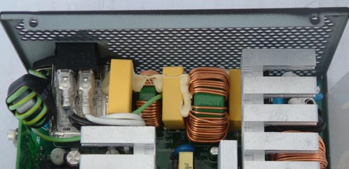
The filtering stage is taken really seriously in the OP650. We found an EMI-filter which is basically there to prevent interferences from the power supply going back into the AC source. The three yellow blocks between the ferrite coils are called X-capacitors and the Y-caps are positioned on the far right side under the heatsinks. Beside this is the rectifier bridge which converts the alternating current into direct current. Silverstone placed it direct on the primary heatsink in order to help dissipate the heat generated by the rectifier.
After opening the housing we are presented with a very clean and systematic arrangement of components. Firstly, the two big heatsinks reveal the first signs of the old Etasis crew. In the most recent designs from Etasis, we find power supplies built with two printed circuit boards that still fit into a standard sized housing. This was made possible through the selection of components which are very short.
The same is clearly visible on first sight in our Silverstone Olympia power supply. Where other manufacturers are using a big capacitor on the primary section, Silverstone designed their PSU using three smaller ones to fit under the massive heatsink. The second difference to most other power supplies is that there are three transformers in the middle of the PCB. Normally this is implemented with one big transformer used to generate all outputs to the PC and a smaller transformer to generate the 5v stand-by rail.
Filtering stage
The filtering stage is taken really seriously in the OP650. We found an EMI-filter which is basically there to prevent interferences from the power supply going back into the AC source. The three yellow blocks between the ferrite coils are called X-capacitors and the Y-caps are positioned on the far right side under the heatsinks. Beside this is the rectifier bridge which converts the alternating current into direct current. Silverstone placed it direct on the primary heatsink in order to help dissipate the heat generated by the rectifier.


46 Comments
View All Comments
Araemo - Friday, July 13, 2007 - link
That makes sense, and makes me think my guess about the 20A limit is possibly a contributing factor - It would be a safety issue if someone hung 40A worth of fans, lights, motorized case windows, whatever you want.. off of one pair of wires (IE, one molex connector feeding into the mass of extenders and passthrough connectors that most fans and lights I've seen use.).You'd likely overheat the wires carrying all that power, if not the connectors as well, which could cause fire or electrocution hazards.
While a GPU may draw significantly more than 20A, they are also using 3 pairs now, so the actual power draw will be closer to 20A per pair.
DerekWilson - Friday, July 13, 2007 - link
The PCIe V2.0 PSUs I've seen suggest only using connectors from the same 12V rail for PCIe graphics cards -- because if you don't, you'll be connecting the common from two different 12V rails together.This can cause issues.
If a graphics card has one 4pin and 1 8pin connector, like the HD 2900 XT, the GPU can potentially draw up to 225W from a single 12V rail through 2x PCIe graphics power connectors (3 pairs). That's about 19 amps through one rail for one PSU, but not over each pair.
SilthDraeth - Friday, July 13, 2007 - link
They explained it.The Intel ATX standard calls for no more than 20 Amps per 12V rail. So in order to avoid maxing out a single 12V rail at 20 Amps, PSUs have multiple rails support up to 20 Amps each.
If you use a single rail that can max out at 54 Amps as stated here, then you do not need the additional rails, but you are going against the ATX standard.
Duraz0rz - Friday, July 13, 2007 - link
Also, I didn't see if there was a reason that it was advertised as a single rail, yet you have 4 12V rails.Nice article...really love the line curves for the load outputs. One thing I noticed missing is ripple testing. Any reason why it's not here?
SilthDraeth - Friday, July 13, 2007 - link
That confused me as well. I think they mentioned that the PSU supposedly includes an ability to turn the other rails off, but it doesn't work, and it always has 4. They did state the PCB was originally designed for 4 rails.Duraz0rz - Friday, July 13, 2007 - link
Nevermind...disregard my statement about the ripple testing. I probably just missed it in the original article after skimming the comments from it :)