The Single 12V Rail SilverStone Olympia OP650
by Christoph Katzer on July 13, 2007 12:00 PM EST- Posted in
- Cases/Cooling/PSUs
Temperatures
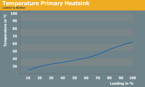
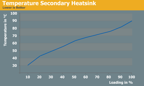
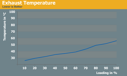
Temperatures inside of the power supply are a very important design aspect and difficult to handle by the manufacturers. The heatsinks need to have a decent size while still letting air through to cool down other components on the PCB. The primary heatsink does not get as hot as the secondary does. At the beginning of each test we connect two temperature diodes to the heatsinks to measure the increasing heat. We are then able to compare these results with the speed of the fan and the exhausted air. With hot heatsinks and cold exhausted air the power supply clearly has a problem with bad airflow or bad heatsink-design.
During the test the primary heatsink reached a temperature of just 60°C which was exactly the same temperature the exhausted air had. The secondary heatsink reached just about 90°C which is quite hot. With just 38 dB(A) and a fan speed of 2300 rpm this power supply had a fan as powerful as any other and should have cooled things a little better. This makes us question whether the heatsink design could have been better, or if a larger heatsink would have made more sense. Compared to each other the primary heatsink has around 30-40% bigger volume than the secondary. Soon we will test the 850W version of this series which will give us more insight into whether or not this is a general issue with Silverstone's heatsink design.


46 Comments
View All Comments
Araemo - Friday, July 13, 2007 - link
That makes sense, and makes me think my guess about the 20A limit is possibly a contributing factor - It would be a safety issue if someone hung 40A worth of fans, lights, motorized case windows, whatever you want.. off of one pair of wires (IE, one molex connector feeding into the mass of extenders and passthrough connectors that most fans and lights I've seen use.).You'd likely overheat the wires carrying all that power, if not the connectors as well, which could cause fire or electrocution hazards.
While a GPU may draw significantly more than 20A, they are also using 3 pairs now, so the actual power draw will be closer to 20A per pair.
DerekWilson - Friday, July 13, 2007 - link
The PCIe V2.0 PSUs I've seen suggest only using connectors from the same 12V rail for PCIe graphics cards -- because if you don't, you'll be connecting the common from two different 12V rails together.This can cause issues.
If a graphics card has one 4pin and 1 8pin connector, like the HD 2900 XT, the GPU can potentially draw up to 225W from a single 12V rail through 2x PCIe graphics power connectors (3 pairs). That's about 19 amps through one rail for one PSU, but not over each pair.
SilthDraeth - Friday, July 13, 2007 - link
They explained it.The Intel ATX standard calls for no more than 20 Amps per 12V rail. So in order to avoid maxing out a single 12V rail at 20 Amps, PSUs have multiple rails support up to 20 Amps each.
If you use a single rail that can max out at 54 Amps as stated here, then you do not need the additional rails, but you are going against the ATX standard.
Duraz0rz - Friday, July 13, 2007 - link
Also, I didn't see if there was a reason that it was advertised as a single rail, yet you have 4 12V rails.Nice article...really love the line curves for the load outputs. One thing I noticed missing is ripple testing. Any reason why it's not here?
SilthDraeth - Friday, July 13, 2007 - link
That confused me as well. I think they mentioned that the PSU supposedly includes an ability to turn the other rails off, but it doesn't work, and it always has 4. They did state the PCB was originally designed for 4 rails.Duraz0rz - Friday, July 13, 2007 - link
Nevermind...disregard my statement about the ripple testing. I probably just missed it in the original article after skimming the comments from it :)