EVGA 680i LT SLI: NVIDIA's 680i Cost Reduced
by Gary Key on March 28, 2007 4:00 AM EST- Posted in
- CPUs
Overclocking - E6300
We were easily able to reach a final benchmark stable setting of 7x500 FSB resulting in a clock speed of 3500MHz. We were able to run our OCZ Flex PC2-9200 and Corsair PC2-8888 at the reported timings with a 1T Command Rate enabled with 2.30V. However, when overclocking we had to run our standard OCZ Flex PC2-6400 at 2T command rates due to the next voltage step being 2.30V, a setting that is not recommended for the ProMOS chips (2.250V is our recommended limit for 24/7 operation). Vdroop was very acceptable on this board during overclocking with an average drop of .02 ~.03V during load testing with our E6300.
Testing with our new OCZ Flex PC2-6400 CAS3 (standard memory installed) and G.Skill F2-6400CL4D-2GBHK modules based on the ProMOS IC chips resulted in great success on this board. The OCZ Flex PC2-6400 was able to run at DDR2-800 speeds with timings at 3-4-3-9 2T at 2.15V and the G.Skill F2-6400CL4D at 4-3-3-8 2T at 2.15V on our other NVIDIA boards but we had to use the 2.20V setting. The remaining memory timings are set to Auto as is standard in our testing and manually setting these timings resulted in minimal performance gains. We did notice in 4GB testing that we had to change our OCZ Flex PC2-6400 CAS3 memory timings to 3-4-4-12 2T at 2.20V for stable 24/7 operation in a variety of applications.
Overclocking - E6600
After trying numerous settings and voltages we finally found a benchmark stable setting of 9x425 FSB resulting in a clock speed of 3825MHz. We did find the typical FSB hole around 416FSB that continued until 422FSB. We were able to post and complete benchmark testing at 432FSB but could not pass dual Prime95 at that setting. Vdroop was acceptable during overclocking with an average drop of .03 ~.04V during load testing with our E6600. We generally found that without decent airflow around the CPU and memory locations that our maximum FSB was near 410 MHz with this configuration.
We dropped the multiplier on our E6600 to seven and were able to reach 500 FSB. We entered XP at 7x518 but the board was not stable due to a lack of higher FSB/SPP/MCP voltages. At first we thought the board was locked at 500FSB but once again we found FSB holes but this time they ranged from 502 to 516. We jokingly started to refer to this board as Swiss cheese during testing as everywhere we turned there was another FSB hole. If NVIDIA had offered VTT and GTL Ref Voltage options in the BIOS we are sure several of our holes could have been solved but we were still able to work around most of them.
In our overclock testing we were able to extract an 1133MHz memory speed at 5-5-5-15 2T timings with our OCZ Flex PC2-6400. This is the highest speed we have reached with this memory and at synced speeds we were able to reach DDR2-850 with timings at 3-4-4-9 2T on 2.20V. We dropped in our OCZ Flex PC2-9200 and Corsair PC2-9136 modules with both being able to reach DDR2-1275 with 5-5-4-12 2T timings at 2.30V. Memory performance and stability was excellent once the board was dialed in.
| EVGA 680i LT SLI Dual Core Overclocking Testbed |
|
| Processor: | Intel Core 2 Duo E6300 Dual Core, 1.86GHz, 2MB Unified Cache 1066FSB, 7x Multiplier |
| CPU Voltage: | 1.4500V (default 1.3250V) |
| NB Voltage: | 1.40V |
| FSB Voltage: | 1.40V |
| Cooling: | Tuniq 120 Air Cooling |
| Power Supply: | OCZ ProXStream 1000W |
| Memory: | OCZ Flex XLC PC2-6400 (2x1GB) (ProMOS Memory Chips) |
| Video Cards: | 1 x MSI 8800GTX |
| Hard Drive: | Western Digital 150GB 10,000RPM SATA 16MB Buffer |
| Case: | Cooler Master CM Stacker 830 |
| Maximum OC: | 500x7 (3-4-3-9 2T, 800MHz, 2.20V), CPU 1.4500V 3500MHz (+88% FSB/CPU) |
| . | |
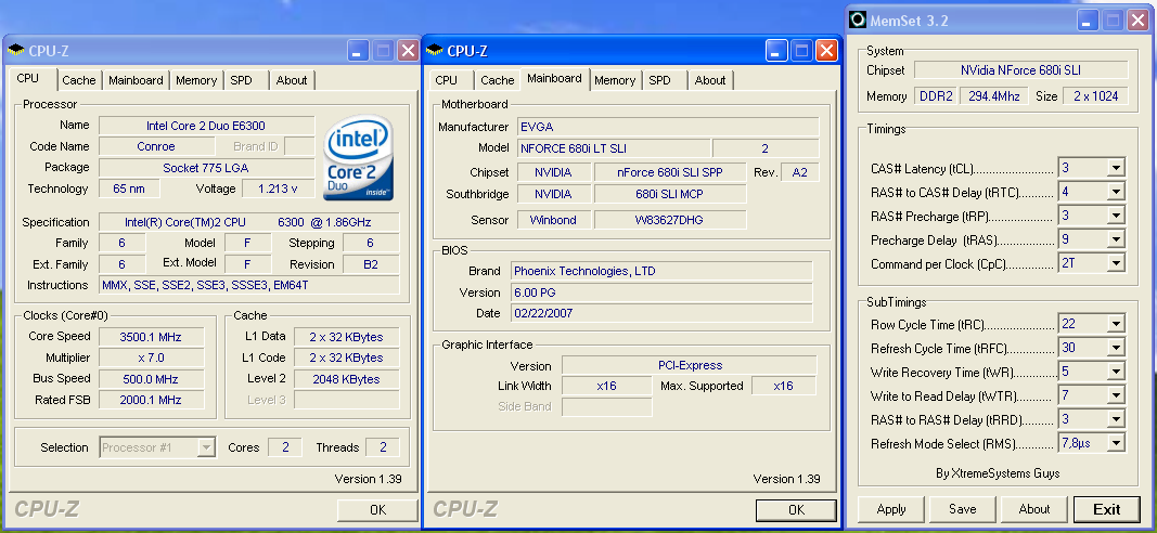 |
| Click to enlarge |
We were easily able to reach a final benchmark stable setting of 7x500 FSB resulting in a clock speed of 3500MHz. We were able to run our OCZ Flex PC2-9200 and Corsair PC2-8888 at the reported timings with a 1T Command Rate enabled with 2.30V. However, when overclocking we had to run our standard OCZ Flex PC2-6400 at 2T command rates due to the next voltage step being 2.30V, a setting that is not recommended for the ProMOS chips (2.250V is our recommended limit for 24/7 operation). Vdroop was very acceptable on this board during overclocking with an average drop of .02 ~.03V during load testing with our E6300.
Testing with our new OCZ Flex PC2-6400 CAS3 (standard memory installed) and G.Skill F2-6400CL4D-2GBHK modules based on the ProMOS IC chips resulted in great success on this board. The OCZ Flex PC2-6400 was able to run at DDR2-800 speeds with timings at 3-4-3-9 2T at 2.15V and the G.Skill F2-6400CL4D at 4-3-3-8 2T at 2.15V on our other NVIDIA boards but we had to use the 2.20V setting. The remaining memory timings are set to Auto as is standard in our testing and manually setting these timings resulted in minimal performance gains. We did notice in 4GB testing that we had to change our OCZ Flex PC2-6400 CAS3 memory timings to 3-4-4-12 2T at 2.20V for stable 24/7 operation in a variety of applications.
Overclocking - E6600
| EVGA 680i LT SLI Dual Core Overclocking Testbed |
|
| Processor: | Intel Core 2 Duo E6600 Dual Core, 2.4GHz, 4MB Unified Cache 1066FSB, 9x Multiplier |
| CPU Voltage: | 1.4750V / 1.4500 (default 1.3250V) |
| NB Voltage: | 1.40V |
| FSB Voltage: | 1.40V |
| Cooling: | Tuniq 120 Air Cooling |
| Power Supply: | OCZ ProXStream 1000W |
| Memory: | OCZ Flex XLC PC2-6400 (2x1GB) (ProMOS Memory Chips) |
| Video Cards: | 1 x MSI 8800GTX |
| Hard Drive: | Western Digital 150GB 10,000RPM SATA 16MB Buffer |
| Case: | Cooler Master CM Stacker 830 |
| Maximum CPU OC: | 425x9 (3-4-3-9 2T, 799MHz, 2.20V), CPU 1.4750V 3825MHz (+59%) |
| Maximum FSB OC: | 500x7 (3-4-3-9 2T, 800MHz, 2.20V), CPU 1.4500V 3500MHz (+88% FSB) |
| . | |
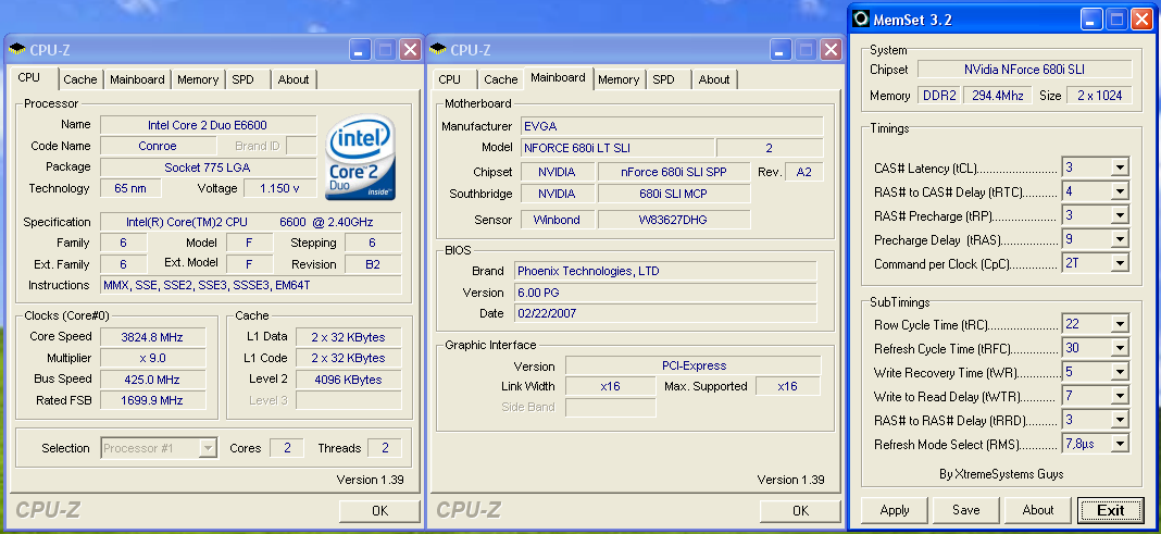 |
| Click to enlarge |
After trying numerous settings and voltages we finally found a benchmark stable setting of 9x425 FSB resulting in a clock speed of 3825MHz. We did find the typical FSB hole around 416FSB that continued until 422FSB. We were able to post and complete benchmark testing at 432FSB but could not pass dual Prime95 at that setting. Vdroop was acceptable during overclocking with an average drop of .03 ~.04V during load testing with our E6600. We generally found that without decent airflow around the CPU and memory locations that our maximum FSB was near 410 MHz with this configuration.
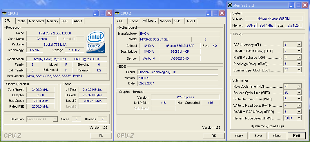 |
| Click to enlarge |
We dropped the multiplier on our E6600 to seven and were able to reach 500 FSB. We entered XP at 7x518 but the board was not stable due to a lack of higher FSB/SPP/MCP voltages. At first we thought the board was locked at 500FSB but once again we found FSB holes but this time they ranged from 502 to 516. We jokingly started to refer to this board as Swiss cheese during testing as everywhere we turned there was another FSB hole. If NVIDIA had offered VTT and GTL Ref Voltage options in the BIOS we are sure several of our holes could have been solved but we were still able to work around most of them.
In our overclock testing we were able to extract an 1133MHz memory speed at 5-5-5-15 2T timings with our OCZ Flex PC2-6400. This is the highest speed we have reached with this memory and at synced speeds we were able to reach DDR2-850 with timings at 3-4-4-9 2T on 2.20V. We dropped in our OCZ Flex PC2-9200 and Corsair PC2-9136 modules with both being able to reach DDR2-1275 with 5-5-4-12 2T timings at 2.30V. Memory performance and stability was excellent once the board was dialed in.


16 Comments
View All Comments
Stele - Wednesday, March 28, 2007 - link
It boils down to the engineering headroom put into the PWM design. Let's say the maximum supply current anticipated from a generation of CPUs is 50A (usually from datasheets and/or design guidelines from the CPU manufacturer). Motherboard designers can design their PWM to be just sufficient for this - most notably, the MOSFETs chosen may be those that can handle around 75A - or they can build some headroom in and choose MOSFETs capable of, say, 100A.
The former design philosophy saves cost, and after all it gets the job done. However, since the components would be running near their design limit, they would generate quite a bit of heat... especially during spikes of load and/or when new CPUs with even higher current draw (e.g. quad-core CPUs) show up.
The latter design philosophy is more expensive, but because the components would be running well below their rated spec, they fare much better in terms of thermal dissipation (and hence efficiency, as less power is lost as heat). The lower running temperatures also help improve the reliability of the components since less thermal stresses are present. Furthermore, when current loads increase - be it due to sudden load spikes and/or power-hungry CPUs and/or overclocking - they still have a lot of headroom, and so are able to handle the extra load without breaking a sweat. This results in better stability and again, lower heat dissipation compared to lower-spec'ed components at the same load.
In view of this, perhaps one other area that Anandtech could look at when reviewing motherboards is to have an IR thermometer handy (the ones that you can point and measure temperatures of surfaces remotely with) and perhaps measure the temperatures of the chipset and PWM (or at least the temperatures of their heatsinks) at idle and load. It may not be perfect (especially when heatpiped, and a hotter heatsink could also mean that the heat flow from the component to the heatsink is good due to good thermal contact) but imho at least it would give a useful ballpark figure.
Stele - Wednesday, March 28, 2007 - link
Pretty good review, critically assessing the chipset in light of theory (paper specs) as well as reality (actual value for money based on real-world prices and competiting products).IMHO, Nvidia's attempt to create a lower-cost version of the 680i SLI by limiting BIOS options and tossing the odd feature out (like passive chipset cooling and two USB/one network port) seems a little clumsy at best... Instead, I think the hybrid chipset combination used in, for example, the Asus P5N32-E SLI Plus is a more elegant solution. As this review demonstrated, the BIOS options do not necessarily cap the LT's overclocking capability enough to prevent it from being a threat to the 680i SLI's exclusive turf. Indeed, it might well turn out that the latter's sales would not be jeopardised by the LT anyway - not because of the arbitrarily imposed limitations, but because of the almost non-existent price difference between boards based on the two chipsets, considering the lost features.
Meanwhile, other reviews of the P5N32-E SLI Plus have noted that the MCP used is that from the AMD-platform 590 SLI chipset. I wonder if, other than the slight rearrangement of PCI-Express lanes, there are any real differences (e.g. revised/improved networking/disk controller engines etc) between the two MCPs? Or are these blocks nothing more than carried over directly from the 590 SLI? It would be great if Anandtech could look into that.
Lastly, a tiny note - it's a little amusing to note how it must be a bit pedantic to have to spell out the full name of the 'solid' capacitors used... at least Anandtech strives hard to get it right! :) Really, though, for the kind of 'solid' capacitors that we're talking about on most motherboards, "aluminium solid electrolytic capacitors" or even just "solid electrolytic capactitors" (vs. 'regular' (liquid) electrolytic) would do perfectly. Conductive polymer capacitors are generally (though not restricted to) the little rectangular ones such as the ones seen on Asus RoG boards as well as the P5N32-E SLI Plus. Just a thought :)
yyrkoon - Wednesday, March 28, 2007 - link
Well, about the capacitors, I know as per some OEM, anandtech was calling them 'solid state capacitors', which you sound like you know enough about electronics to know this is wrong. Anyhow, several readers, including myself called 'foul', and there you have it . . .JarredWalton - Wednesday, March 28, 2007 - link
There were a few complaints when he used "solid capacitors", so I guess the full name is the safe way to go. LOLStele - Wednesday, March 28, 2007 - link
Oh very true! "Solid capacitors" and "solid state capacitors" (as yyrkoon rightly commented) are both commonly used on many hardware sites, and are both inaccurate. One reason for the repeated complaints, iirc, is that we were simply oscillating between one inaccurate term and another. :P"Solid electrolytic capacitors"... now that is perfectly acceptable, despite a difference of one word. The devil, as they say, is in the details. ;)
yyrkoon - Wednesday, March 28, 2007 - link
You did the right thing Jarred, you know how picky 'us' readers are ;)