Intel Core Duo: AOpen i975Xa-YDG to the Rescue
by Gary Key on May 4, 2006 8:00 AM EST- Posted in
- Motherboards
Board Layout
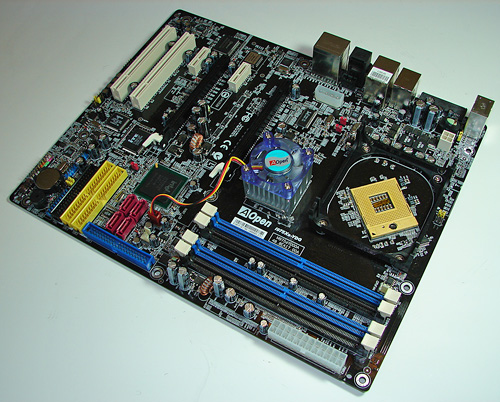
AOpen designed a very well laid out board with all major connections easily reached. The board is lacking most clearance issues and was very easy to install in a mid-size ATX case. The board features an excellent voltage regulator power design along with Rubycon capacitors that yielded superb stability and overclocking results. Here's an enhanced close-up of the capacitors area.
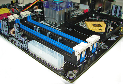
The DIMM module slots' color coordination is correct for dual channel setup based upon the premise of utilizing different colors for each memory bank. The memory modules are easy to install with a full size video card placed in the first PCI Express X16 slot. The 24-pin ATX power connector is located along the upper edge of the board and below the memory modules.
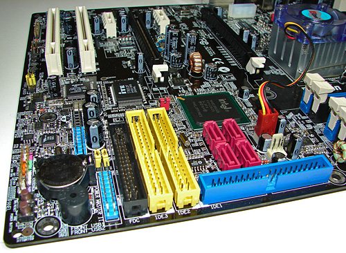
The Intel IDE port connector is the blue IDE socket located along the edge of the board and to the right of the memory modules. This port did not present any connection issues in our mid-size ATX case. The system and Northbridge fan headers are located above the IDE1 port and to the left of the Intel SATA ports.
The four Intel SATA ports are a reddish-pink color and are conveniently located below the Intel ICH7 Southbridge. The SATA ports feature the newer clamp and latch design. We found the positioning of the SATA ports to be excellent when utilizing the PCI-E slots or the Intel IDE port connector. The Intel ICH7 Southbridge does not require a heatsink in this application.
The two yellow IDE port connectors are provide by the ITE chip and are located below the Intel SATA ports. These ports did not present any connection issues in our mid-size ATX case although they could potentially interfere with the SATA ports or might cause a cable length issue in full size ATX cases.
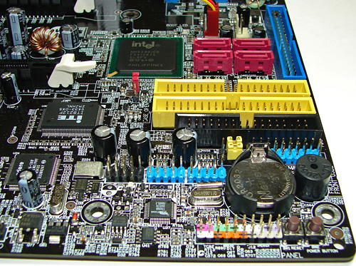
The black floppy drive connector is positioned below the ITE IDE ports. The location of this connector is not ideal and actually the whole point of having a floppy drive connector is becoming moot with the wide spread availability of USB floppy or flash drives along with BIOS support for boot purposes.
The blue IR port is located below the floppy drive connector and above the battery. This connector is required for the Remote Control unit. Take note of the yellow jumpers; if they are not installed correctly the Remote Control unit will not operate correctly. The jumper configuration is not mentioned in the manual.
The nine pins on the black plastic base provide an additional IEEE-1394 connector; this connection is located to the left of the two additional blue USB connectors - not to be confused with the blue IR connection. The chassis panel connections are located at the bottom edge of the board below the battery. AOpen also provides onboard reset and power buttons, a feature that is greatly appreciated and very useful for boards not in a case. Last and actually least used is the clear CMOS jumper block that is a traditional jumper design located below the Intel ICH7 and to the left of the ITE IDE connectors. We did not utilize this jumper throughout our two weeks of testing this board and AOpen should be commended for their BIOS self recovery system and general board stability.
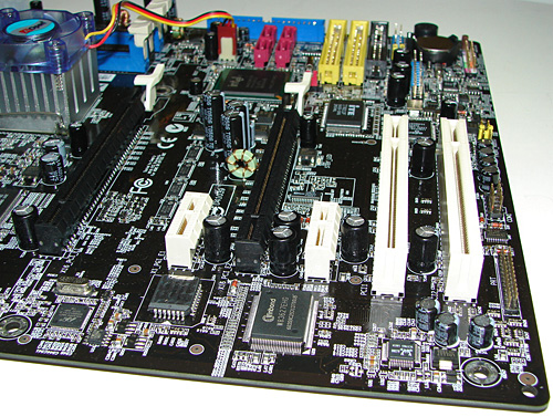
The board comes with (2) physical PCI Express X16 connectors, (2) PCI Express X1 connectors, and (2) PCI 2.3 connectors. The layout of this design offers a good balance of expansion slots for a mainstream board while providing excellent clearance space for card utilization. AOpen designed a two slot opening between the first X16 PCI-E connector and the first X1 PCI-E connector, allowing you to utilize the X1 connector with a dual slot cooling system.
The primary PCI Express X16 connector is located to the far left of the slot areas. The first PCI Express X1 connector is located next, followed by the secondary PCI Express X16 connector. The second PCE Express X1 connector is next, and then last are the (2) PCI slots. Although there are two physical X16 connectors available on the board, they operate in X8 PCI-E mode in multi-GPU or CrossFire mode.
We did not have any issues installing our EVGA 7900GTX 512MB or ATI X1900XTX video cards in the first or second X16 PCI Express slots. A dual slot card located in the second X16 connector will physically render the second PCI Express X1 slot useless. There were no issues utilizing this slot with video cards containing single slot cooling systems.
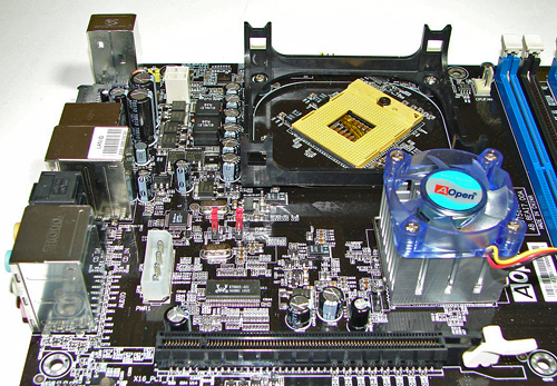
Returning to the CPU socket area, we find an ample amount of room for alternative cooling solutions. We utilized the supplied AOpen heatsink/fan but also verified a couple of Socket-478/9 cooling solutions would fit in this area during our tests. However, due to the low voltages utilized and resulting thermal output, the supplied AOpen heatsink/fan worked fine throughout our testing. The CPU socket is rotated at a 45 degree angle, which we have seen in past Pentium-M configurations.
The Intel 975X Northbridge is actively cooled with a medium sized heatsink/fan unit that did not interfere with any installed peripherals. In fact this unit kept the chipset cool enough that additional chipset voltage was not a factor in our overclocking tests. Our only concern is the lifespan of the fan but it is very quiet during operation. Our advice to AOpen is to install a more effective passive heatsink design and drop the fan as our overclock testing showed no differences between the fan operating or not.
AOpen places the four-pin 12v auxiliary power connector at the top of the CPU socket area but out of the way of aftermarket cooling solutions. The four-pin Molex power connector is located above the first X16 PCI-E connector and must be utilized for multi-GPU or CrossFire operation. This connector is located in a position that can hamper airflow with cabling that crosses directly over the CPU heatsink/fan, though power supplies with longer cables will usually allow you to route cables around the CPU.
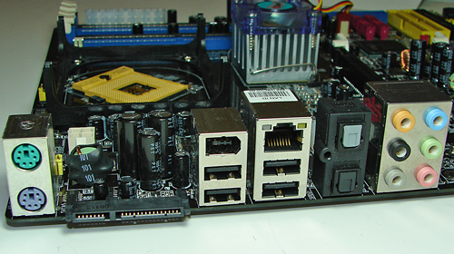
The rear panel contains the standard PS/2 mouse and keyboard ports, LAN port, and 4 USB ports. The LAN (RJ-45) port has two LED indicators representing Activity and Speed of the connection. The audio panel consists of 6 ports that can be configured for 2, 4, 6, and 8-channel audio connections. The rear panel also has two S/PDIF optical ports (In/Out), IEEE-1394 port, and a powered external SATA 3Gb/s port.
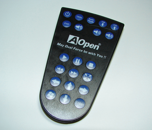
One of the more interesting options we have seen in a motherboard kit is this remote control unit from AOpen. Its main purpose is to control Windows Media Player functions but AOpen designed system on/off and FSB overclocking capability into the mix. Both of these functions proved valuable during the course of our testing, especially the FSB settings as we explored the overclocking limits of our board. (Just don't let your toddler have too much fun pressing buttons on the remote!)


81 Comments
View All Comments
BrownTown - Thursday, May 4, 2006 - link
Conroe prices have been out for like 4 months now, they are anything but overpriced, actually way underpriced when it comes to performance/$$$.