Features
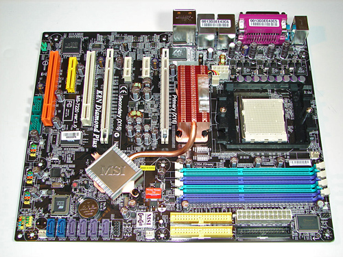
MSI designed a very well laid out board with all major connections easily reached except for the eight-pin ATX power connector when a larger air or water cooling system is utilized. The MSI layout provides excellent clearance for cards and components and was easy to install in a mid-size ATX case. Although the board features a 3-phase voltage regulator power design it provided excellent stability, power regulation, and allowed for an impressive level of overclocking. The board provides 2 chassis, 1 CPU, and 1 Northbridge fan header, but as mentioned the BIOS does not allow temperature based fan control of the chassis headers.
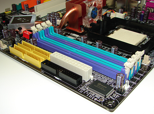
The DIMM module slots are not color coordinated correctly for dual channel setup. If the user utilizes the two green or two purple memory slots then the board will reward you with single channel operation unless all four slots are utilized. Also note that if you only use two DIMMs, a correct dual channel setup will place the DIMMs in adjacent slots; this will generally create slightly higher RAM temperatures, though in practice this will only be a problem for more extreme overclocks. The memory modules are fairly easy to install with a full size video card placed in the first PCI Express x16 slot.
The black floppy drive and yellow IDE primary connectors are conveniently placed along the edge of the board. The white 24-pin ATX power connector and yellow secondary IDE connector are located in between the last memory module slot and the floppy and secondary IDE connectors respectively. This layout should work very well for most users.
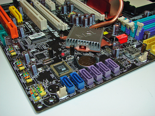
The nForce4 SATA port connectors are color coded purple while being located along the board's edge and beneath the battery. The SATA port connectors did not present any connection issues when utilizing the board in SLI operation. The second system fan header is located to the right of the SATA ports and below the MSI Core Cell chipset and red labeled memory voltage switch block. The nForce4 SLI chipset (i.e. Southbridge) is passively cooled with a low rise heatsink and located in a position that does not interfere with the secondary PCI Express x16 or primary 32-bit PCI slot when occupied. The heatsink is attached to the Northbridge fan/heatsink via a heatpipe design.
The blue Silicon Image SATA ports are located below the BIOS chip and to the left of the nForce4 SATA connectors. The first system fan header is located to the left of the Silicon Image SATA ports followed by the chassis panel connectors. The yellow USB 3/4/5 headers are located along the edge of the board. The CMOS reset block is the red button to the left of the Southbridge. If you ever have occasion to clear the CMOS settings, you'll find the button to be far more convenient than the traditional jumper designs.
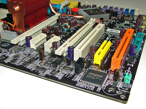
The board comes with (2) physical PCI Express x16 connectors, (2) PCI Express x1 connectors, (1) PCI Express x4 connector, and (2) 32-bit PCI 2.3 connectors. The layout of this design offers a good balance of expansion slots for a mainstream board. The first physical PCI Express x16 connector is color coded white and located uncomfortably close to the C51D Northbridge fan/heatsink unit. The two PCI Express x1 connectors are located next followed by the second white PCI Express x16 connector. The first 32-bit PCI connector is located next and followed by the yellow PCI Express x4 connector and second 32-bit PCI connector that is color coded orange.
We did not have any issues installing our NVIDIA 7900GTX video cards in the first and second x16 PCI Express slots. These dual slot configuration cards will physically render the first PCI Express x1 and 32-bit PCI slots useless. We did not have any issues utilizing these slots with video cards containing single slot cooling systems. Looking back at the slot configuration, we wish MSI would have dropped one of the PCI Express x1 slots for another 32-bit PCI slot, as the number of PCI expansion cards and their usefulness continues to surpass that of PCI-E x1 cards. This is a minor point really, but anyone looking to install two dual slot GPUs with a sound card and a TV tuner will need to opt for a PCI-E tuner card. Unfortunately, there are no PCI-E audio or HDTV solutions at present.
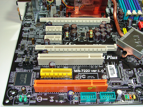
The Front Panel Audio connector and two green IEEE 1394A connectors are located along the edge of the board. If you use both internal Firewire headers, that means you have a total of three Firewire ports - probably more than most people will need, but certainly nothing to complain about. The black CD Audio In connector is located to the left of the first 32-bit PCI connector.
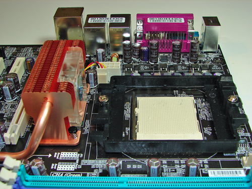
Returning to the CPU socket area, we find a limited amount of room for alternative cooling solutions. We utilized the stock AMD heat sink but also verified several aftermarket cooling systems such as the Thermaltake Big Typhoon and Zalman CNPS9500 would fit in this area during our tests. Due to the high rise fan/heatsink covering the NVIDIA C51D Northbridge chipset, the installation of larger air or water-cooling solutions will be an issue. We were able to install our Tuniq Tower 120 but it rubbed against the Northbridge fan/heatsink.
MSI places the eight-pin ATX12V auxiliary power connector at the top left of the CPU socket area - it works fine with the older four-pin ATX12v connectors as well, although this is not mentioned in the manual. This connector is located in an unusual position and could hamper airflow with cabling that crosses directly over the CPU heatsink/fan. We did not have any issues in our particular setup, but the choice of case and HSF should be made carefully. There is also a four-pin molex connector located to the left of the ATX12V connector that must be utilized for dual card operation - one more cable to potentially route around the CPU area.
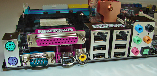
The rear panel contains the standard PS/2 mouse and keyboard, serial, parallel, and 4 USB ports. Located to the right of the serial port and below the parallel port is the IEEE 1394 port and S/PDIF Coaxial out port. Located next are the four USB 2.0 ports with the RJ-45 LAN ports on top. The audio panel is located to the right of these ports and consists of 5 ports that can be configured for 2, 4, 5.1, and 7.1 channel audio connections. The S/PDIF Optical (TOS Link) out port is located to the right of the pink MIC port.
MSI designed a very well laid out board with all major connections easily reached except for the eight-pin ATX power connector when a larger air or water cooling system is utilized. The MSI layout provides excellent clearance for cards and components and was easy to install in a mid-size ATX case. Although the board features a 3-phase voltage regulator power design it provided excellent stability, power regulation, and allowed for an impressive level of overclocking. The board provides 2 chassis, 1 CPU, and 1 Northbridge fan header, but as mentioned the BIOS does not allow temperature based fan control of the chassis headers.
The DIMM module slots are not color coordinated correctly for dual channel setup. If the user utilizes the two green or two purple memory slots then the board will reward you with single channel operation unless all four slots are utilized. Also note that if you only use two DIMMs, a correct dual channel setup will place the DIMMs in adjacent slots; this will generally create slightly higher RAM temperatures, though in practice this will only be a problem for more extreme overclocks. The memory modules are fairly easy to install with a full size video card placed in the first PCI Express x16 slot.
The black floppy drive and yellow IDE primary connectors are conveniently placed along the edge of the board. The white 24-pin ATX power connector and yellow secondary IDE connector are located in between the last memory module slot and the floppy and secondary IDE connectors respectively. This layout should work very well for most users.
The nForce4 SATA port connectors are color coded purple while being located along the board's edge and beneath the battery. The SATA port connectors did not present any connection issues when utilizing the board in SLI operation. The second system fan header is located to the right of the SATA ports and below the MSI Core Cell chipset and red labeled memory voltage switch block. The nForce4 SLI chipset (i.e. Southbridge) is passively cooled with a low rise heatsink and located in a position that does not interfere with the secondary PCI Express x16 or primary 32-bit PCI slot when occupied. The heatsink is attached to the Northbridge fan/heatsink via a heatpipe design.
The blue Silicon Image SATA ports are located below the BIOS chip and to the left of the nForce4 SATA connectors. The first system fan header is located to the left of the Silicon Image SATA ports followed by the chassis panel connectors. The yellow USB 3/4/5 headers are located along the edge of the board. The CMOS reset block is the red button to the left of the Southbridge. If you ever have occasion to clear the CMOS settings, you'll find the button to be far more convenient than the traditional jumper designs.
The board comes with (2) physical PCI Express x16 connectors, (2) PCI Express x1 connectors, (1) PCI Express x4 connector, and (2) 32-bit PCI 2.3 connectors. The layout of this design offers a good balance of expansion slots for a mainstream board. The first physical PCI Express x16 connector is color coded white and located uncomfortably close to the C51D Northbridge fan/heatsink unit. The two PCI Express x1 connectors are located next followed by the second white PCI Express x16 connector. The first 32-bit PCI connector is located next and followed by the yellow PCI Express x4 connector and second 32-bit PCI connector that is color coded orange.
We did not have any issues installing our NVIDIA 7900GTX video cards in the first and second x16 PCI Express slots. These dual slot configuration cards will physically render the first PCI Express x1 and 32-bit PCI slots useless. We did not have any issues utilizing these slots with video cards containing single slot cooling systems. Looking back at the slot configuration, we wish MSI would have dropped one of the PCI Express x1 slots for another 32-bit PCI slot, as the number of PCI expansion cards and their usefulness continues to surpass that of PCI-E x1 cards. This is a minor point really, but anyone looking to install two dual slot GPUs with a sound card and a TV tuner will need to opt for a PCI-E tuner card. Unfortunately, there are no PCI-E audio or HDTV solutions at present.
The Front Panel Audio connector and two green IEEE 1394A connectors are located along the edge of the board. If you use both internal Firewire headers, that means you have a total of three Firewire ports - probably more than most people will need, but certainly nothing to complain about. The black CD Audio In connector is located to the left of the first 32-bit PCI connector.
Returning to the CPU socket area, we find a limited amount of room for alternative cooling solutions. We utilized the stock AMD heat sink but also verified several aftermarket cooling systems such as the Thermaltake Big Typhoon and Zalman CNPS9500 would fit in this area during our tests. Due to the high rise fan/heatsink covering the NVIDIA C51D Northbridge chipset, the installation of larger air or water-cooling solutions will be an issue. We were able to install our Tuniq Tower 120 but it rubbed against the Northbridge fan/heatsink.
MSI places the eight-pin ATX12V auxiliary power connector at the top left of the CPU socket area - it works fine with the older four-pin ATX12v connectors as well, although this is not mentioned in the manual. This connector is located in an unusual position and could hamper airflow with cabling that crosses directly over the CPU heatsink/fan. We did not have any issues in our particular setup, but the choice of case and HSF should be made carefully. There is also a four-pin molex connector located to the left of the ATX12V connector that must be utilized for dual card operation - one more cable to potentially route around the CPU area.
The rear panel contains the standard PS/2 mouse and keyboard, serial, parallel, and 4 USB ports. Located to the right of the serial port and below the parallel port is the IEEE 1394 port and S/PDIF Coaxial out port. Located next are the four USB 2.0 ports with the RJ-45 LAN ports on top. The audio panel is located to the right of these ports and consists of 5 ports that can be configured for 2, 4, 5.1, and 7.1 channel audio connections. The S/PDIF Optical (TOS Link) out port is located to the right of the pink MIC port.


42 Comments
View All Comments
LoneWolf15 - Tuesday, April 11, 2006 - link
There are TV tuner cards based on ATI's Theater 550 chip, Powercolor makes one, details can be found here:http://www.powercolor.com/product_series_Theater.h...">http://www.powercolor.com/product_series_Theater.h...
Gary Key - Tuesday, April 11, 2006 - link
We are currently reviewing the Powercolor T55E-P03 for an upcoming HTPC article. I think the results against the PCI cards will be interesting. ;-)LoneWolf15 - Wednesday, April 12, 2006 - link
From what I've heard, there's little or no difference in performance. However, the Powercolor would be the card I'd consider for future-proofness.My only disappointment is it doesn't use ATI's Remote Wonder line of remote controls; they include an iR remote of their own choosing instead of the ATI RF model, IIRC.
nullpointerus - Tuesday, April 11, 2006 - link
Interesting, how? Better, worse, wierd, or just unspecified in a frustratingly vague kind of way? ;-)Gary Key - Wednesday, April 12, 2006 - link
Actual throughput was different than the PCI based card, not trying to be vague but I think the article we are putting together will explain it best, new benchmarks, software versus hardware, TV Tuners- single, dual, SD, and HD, single core CPU , dual core CPU, AMD, Intel, NVIDIA, ATI, MCE2005, Linux, PCI, PCI-E, USB, you know just the basics. ;-)
nullpointerus - Wednesday, April 12, 2006 - link
Cool, thanks. I'm looking forward to reading it.ceefka - Tuesday, April 11, 2006 - link
I don't quite get this one. I can imagine it would say something like 1394b can be had on a s939 Gigabyte board for less than $ 100,00 e.g. GA-K8NF9 Ultra. It seems Gigabyte is the only one with 1394b for s939.
Fact is though that there are few F800 devices out there. If you do have one of these, your mobo options are limited.
JarredWalton - Tuesday, April 11, 2006 - link
It should have been "can't be very large" of course. I'm a bit befuddled on how that slipped in there, because I know I corrected that once before. Must have accidentally pasted over the original text at some point.... Ah, well - fixed now regardless.Myrandex - Tuesday, April 11, 2006 - link
I agree too, there is no reason for manufacturer's to not include this. Firewire B devices will not be mass produced without the users with Firewire B ports. I have a Giga-byte s939 SLI mobo with Firewire B on there and I do want to purchase an external enclosure that supports the standard (along with A and USB), but I also wish we would get some highly OCable boards from the likes of Asus or Abit etc. that provides this feature for the future. And also I believe the article is wrong about the price difference being very large, or else you wouldn't see Giga-byte squeezing these into ~$100 boards with other manufacturer's at the same price point including only A (or no firewire at all).Jason
Duplex - Friday, April 14, 2006 - link
1394B to the people!!! Couldn't agree more!--
I also must give credit to MSI for including a parallel and serial port.
There aren't that many people with a printerserver or USB-printer at home (I think).