Understanding Qualcomm's Snapdragon 810: Performance Preview
by Joshua Ho & Andrei Frumusanu on February 12, 2015 9:00 AM EST- Posted in
- SoCs
- Qualcomm
- Mobile
- Gobi
- Snapdragon 810
QFE2550 Antenna Tuner
One of the first areas to explore would be the RF front end, and before we jump into deep discussions we’ll tackle some of the simpler sections first. The QFE25xx antenna tuner is similar to the envelope tracker in the sense that it’s normally not part of the RF front end. I never actually mentioned an envelope tracker or antenna tuner at any step in the introduction. This is because these parts are not part of the basic superheterodyne radio system. However, like envelope tracking, the need for more battery life, faster data, and superior reception has driven the development of new technologies.
To understand how this antenna tuner works, we must introduce the concept of impedance matching and impedance. Impedance seems difficult at first, but is really just a form of resistance in an AC circuit for the purposes of understanding this article. The three components in a circuit that affect impedance are resistors, capacitors, and inductors. Impedance matching is exactly what it sounds like, which is equalizing the impedance at a junction. In transferring energy from an antenna to the RF front end, we must match the impedance between the antenna and front end. This is because if the impedances are mismatched, signal reflects back to the source. In other words, on the receiving side reception becomes weaker if impedance is mismatched, and on the transmission side energy is wasted. One can liken this to a glossy display, as while the vast majority of the light goes through the glass cover, some light is reflected back.
Of course, in the factory the RF system is carefully tuned to ensure that impedance mismatch is as low as possible. However, the real world makes for a difficult situation. The iPhone 4’s death grip behavior is a classic example of how real-world use can disrupt this impedance matching. By bridging two gaps in the metal ring of the iPhone 4, the antenna was detuned and its impedance was altered. As a result, signal became noticeably worse. Combined with the compressed signal representation, this made it possible for a “decent signal” to be completely lost by touching the right place on the phone.
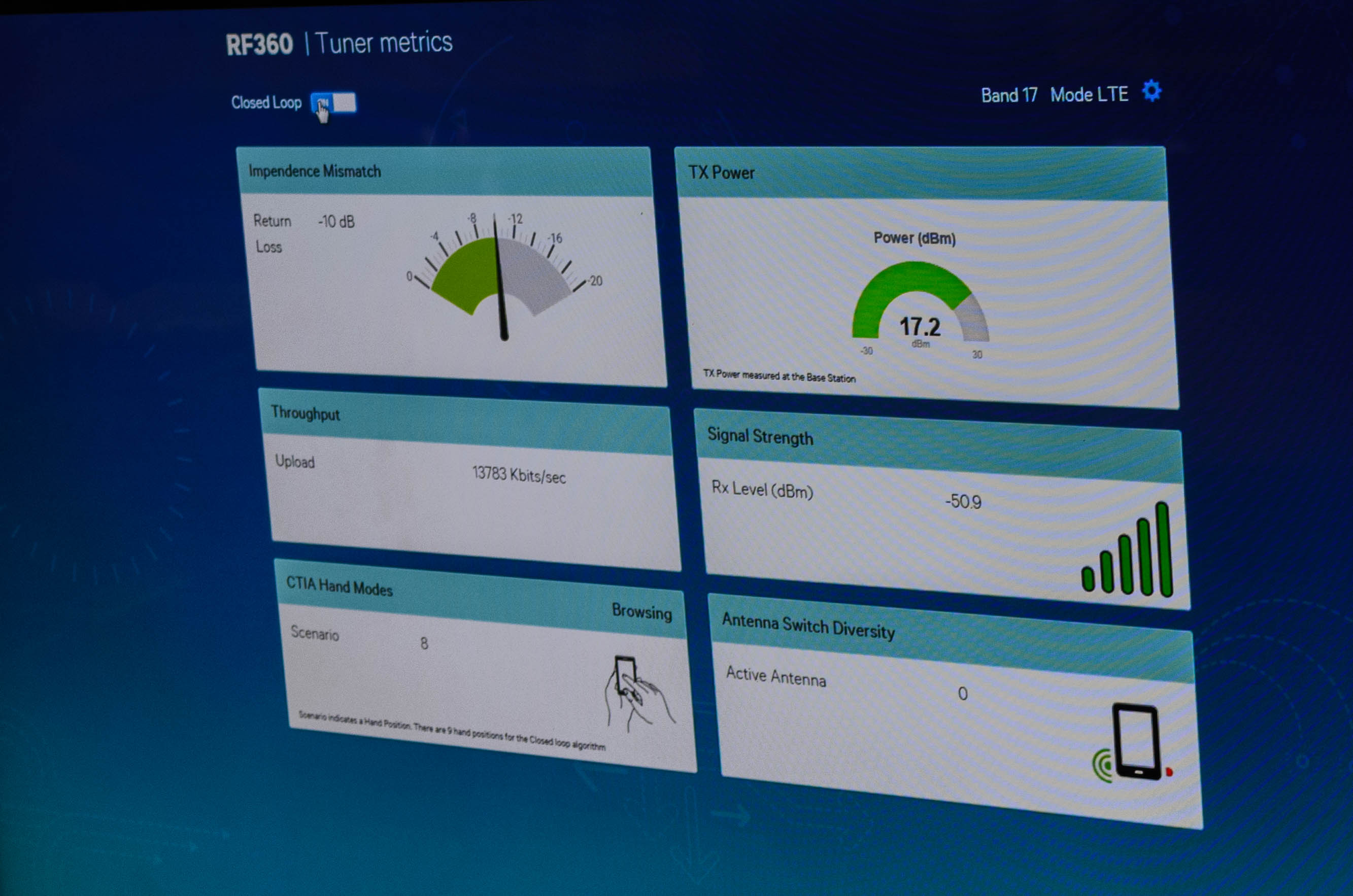
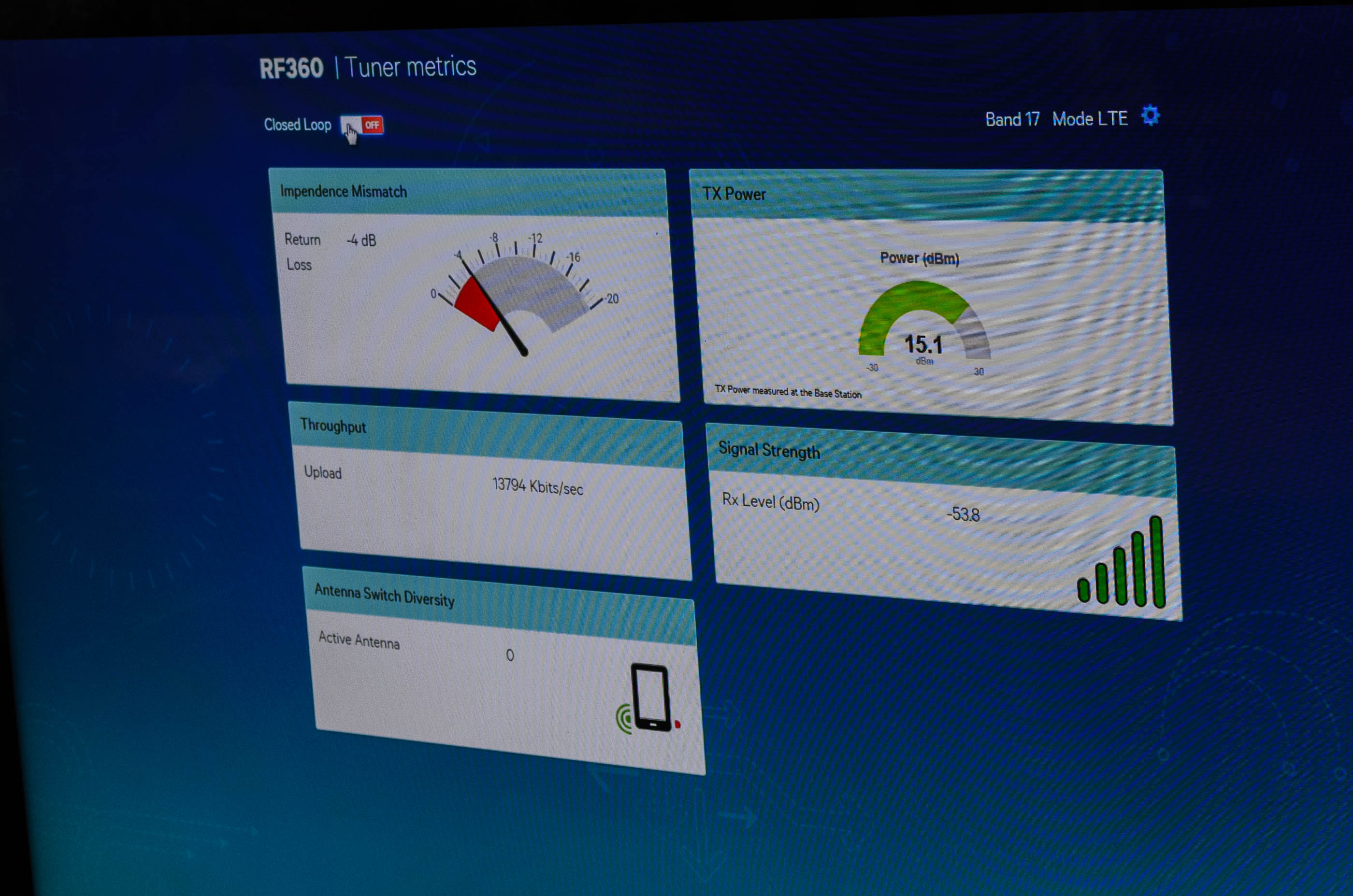
This is where the QFE2550 antenna tuner and similar systems come in. By acting as a voltage-controlled variable capacitor, the baseband can be loaded with information that allows it to predict how much mismatch correction is needed for each detected scenario, which is accomplished with various sensors that can include capacitive touch sensors. Each situation is compensated for by using pre-loaded corrections that are loaded when a given scenario is detected based on frequency change or body loading scenarios. As a result, the efficiency of the antenna is restored as seen in the photo above, although the presence of body loading will inevitably reduce peak power and sensitivity. Such a system can be combined with more information, such as capacitive touch sensors or reflected power measurements to ensure maximum responsiveness and performance. This has the greatest benefit in enabling phones with all-metal unibodies, although other tools such as antenna switched diversity and MIMO can be used to ensure peak reception.
QFE33xx CMOS PA/Switch
Normally, power amplifiers are not worth talking about. However, with the introduction of RF360 Qualcomm has bandied about the concept of a CMOS PA to cover a wide swath of bands rather than just a few. While this sounds interesting, there’s a great deal more nuance to this issue than simply band coverage. First, semiconductor/solid state physics is required to really understand where the debate lies. Of course, there’s really no time to go over this in major depth, but there are a few basics. The transistor is a switch that controls the flow of current. However, there is a limit to how much current can be carried, and there are a few regions in which the relationship between voltage and current differ. The two that we’ll talk about are the linear region and saturation region. The linear region is exactly what it sounds like. Voltage and current are linearly related, following Ohm’s law. The saturation region is where this falls apart, and more voltage is needed to increase current by the same amount, and we see diminishing returns until maximum current is reached.

"IvsV mosfet" by User:CyrilB. Licensed under CC BY-SA 3.0 via Wikimedia Commons
So this is where we see a fundamental difference in the implementation of a CMOS PA and GaAs PA. Gallium arsenide has higher electron mobility, even in saturation mode. This makes it easier for GaAs circuits to switch at incredibly high frequencies such as 60 GHz for WiGig/802.11ad. In addition, unlike silicon-based transistors, gallium arsenide transistors are generally heat-insensitive, and pure GaAs has high resistance and dielectric constant, which means that it serves as an excellent substrate for various components for the same reasons that silicon-on-insulator (SOI) is a good substrate for CMOS logic. In addition, GaAs-based transistors are highly linear in behavior when compared to CMOS technologies, so a GaAs PA can operate much closer to maximum current without clipping the signal.
However, GaAs is not perfect. For one, CMOS logic is impossible to implement using current technologies. This is because unlike current CMOS technology where there are NMOS and PMOS transistors, GaAs-based transistors do not have a p-channel equivalent. As a result, the controls available over a GaAs PA are significantly cruder than what is possible with a CMOS PA. GaAs PAs are also noticeably less efficient at low power levels, also known as the backoff condition. Therefore, CMOS PAs tend to be more power efficient at lower power states as they can have multiple “maximum power states” to scale the PA as needed. In practice, Qualcomm claims that we’re still looking at around a 5-10% efficiency delta at max power when compared to GaAs PAs, which means that CMOS PAs are close to GaAs PAs in efficiency.
Despite the differences in efficiency, a CMOS PA is still a valid option in smartphones due to the fact that a single PA can cover far more bands than an equivalent GaAs PA, as the PAE curve across a spread of frequencies is relatively flat compared to a GaAs PA which is effectively a single peak. In addition, the fact that the PA is built on CMOS means that there is additional integration capability. In its current incarnation, the QFE33xx already has an integrated antenna switch, and there is potential for greater integration with parts that share a similar process node.
This concludes RF360, which gives a broad survey of what’s on the market today. Combined with our previous piece on MDM9x25, it’s possible to get a good idea of the current state of the market. However, the latest and greatest modems and transceivers mean that it’s time to talk about UE category 6, 9, and 10 LTE and the various challenges that come with new capabilities.


119 Comments
View All Comments
aryonoco - Friday, February 13, 2015 - link
Yes, that sentence is totally meaningless.JoshHo - Sunday, February 15, 2015 - link
I didn't write the Geekbench analysis, I'm currently looking into the issue.randymorrisplano - Friday, February 13, 2015 - link
You guys who say 2 or 4k is too much for anything under 6" displays, are seriously are not taking the near future of ubiquitous VR on our handsets. Putting the display that close to the eyes, with magnifying optics, makes it a whole new ballgame.Gigaplex - Friday, February 13, 2015 - link
If I was going to do that, I'd use a VR headset, rather than holding my phone over my eyes.68k - Friday, February 13, 2015 - link
Interesting that Aarch32 get slightly better integer score in Geekbench compared to Aarch64. The lack of HW support for AES and SHA-1 in earlier Aarch32 capable CPUs and the fact that earlier 32 vs 64-bit comparisons has not been done on the same CPU-uarch made it tricky to directly compare results between Aarch32 and Aarch64.Adjusting for the difference in clock frequency between Exynos 5433 and Snapdragon 810, Aarch32 is about 12% fast. Removing the AES result which is an outlier in favor for Exynos, the performance lead for Aarch32 is still about 5%.
Aarch64 seem to do better in the MT cases compared to ST cases, the average lead for Aarch in all ST cases with AES removed is 16%.
dragonsqrrl - Friday, February 13, 2015 - link
So many awesome reviews and previews from Anandtech in the past week. Keep up the good work!lilmoe - Friday, February 13, 2015 - link
At this point of software optimization, I still believe big.LITTLE Core Migration is the way to go. Software isn't yet up to task for GTS, most of that complexity should be handled by hardware.fivefeet8 - Friday, February 13, 2015 - link
Your GFXbench3.0 driver overhead benchmarks seems to be off for the Shield Tablet. Unless maybe Android 5.x is causing a degradation there.sonicmerlin - Friday, February 13, 2015 - link
So how many bands will this new modem be able to support? And why do Apple phones always seem to support more LTE bands than the competition?aryonoco - Friday, February 13, 2015 - link
1) Depends on how many filters and transceivers the OEM fits the phone with. The baseband makes it easier to support more but the actual band support would still be OEM dependant.2) Because Apple does not shy away from high BoM and can cram as much filters and transceivers as they want in order to reduce the number of SKUs. Android manufacturers (unfortunately) don't think like that.