Gigabyte Z77X-UP4 TH Review: Thunderbolt Times Two
by Ian Cutress on September 17, 2012 11:00 AM EST- Posted in
- Motherboards
- Gigabyte
- Z77
- thunder
USB Speed
For this benchmark, we run CrystalDiskMark to determine the ideal sequential read and write speeds for the USB port using our 240 GB OCZ Vertex3 SSD with a SATA 6 Gbps to USB 3.0 converter. Then we transfer a set size of files from the SSD to the USB drive using DiskBench, which monitors the time taken to transfer. The files transferred are a 1.52 GB set of 2867 files across 320 folders – 95% of these files are small typical website files, and the rest (90% of the size) are the videos used in the Sorenson Squeeze test.
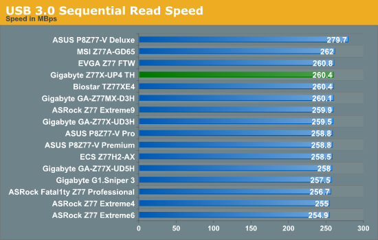
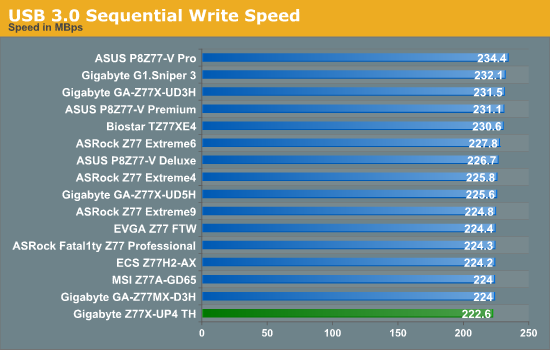
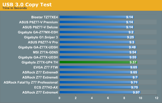
Nothing obscenely wrong comes from the Gigabyte in terms of USB 3.0 speed – even through the write speed was lower than the rest, it came mid-pack in terms of our copy test (the CPU speed may have helped here). Though out USB 3.0 copy test is starting to separate out in terms of vendor – first comes ASUS, then Gigabyte and finally ASRock.
SATA Testing
We also use CrystalDiskMark for SATA port testing on a C300 drive. The sequential test (incompressible data) is run at the 5 x 1000 MB level. This test probes the efficiency of the data delivery system between the chipset and the drive, or in the case of additional SATA ports provided by a third party controller, the efficiency between the controller, the chipset and the drive.
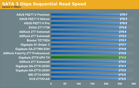
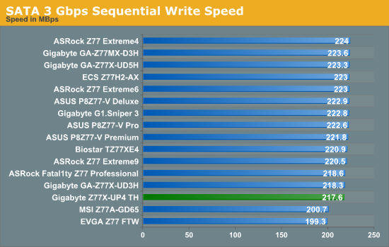
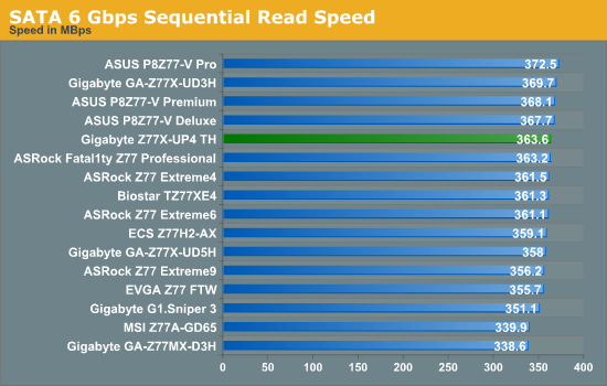

The odd blips we see from some other motherboards in terms of SATA speed are not seen here on the Z77X-UP4 TH, although the writing speed seems a little slow.
DPC Latency
Deferred Procedure Call latency is a way in which Windows handles interrupt servicing. In order to wait for a processor to acknowledge the request, the system will queue all interrupt requests by priority. Critical interrupts will be handled as soon as possible, whereas lesser priority requests, such as audio, will be further down the line. So if the audio device requires data, it will have to wait until the request is processed before the buffer is filled. If the device drivers of higher priority components in a system are poorly implemented, this can cause delays in request scheduling and process time, resulting in an empty audio buffer – this leads to characteristic audible pauses, pops and clicks. Having a bigger buffer and correctly implemented system drivers obviously helps in this regard. The DPC latency checker measures how much time is processing DPCs from driver invocation – the lower the value will result in better audio transfer at smaller buffer sizes. Results are measured in microseconds and taken as the peak latency while cycling through a series of short HD videos - under 500 microseconds usually gets the green light, but the lower the better.
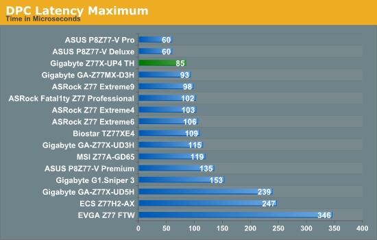
Despite the Z77X-UP4 TH falling victim to the H/W Monitor bug in terms of DPC testing (raising the value to 800+), when turned off the peak DPC Latency was 85 microseconds which is an excellent result.


15 Comments
View All Comments
IanCutress - Monday, September 17, 2012 - link
I have access to a TB device, but it is only the two-bay Little Big disk with a pair of Intel Drives. Can't really stress the TB implementation in terms of peak speeds, and in our copy test it can get anything from 1.1 seconds to 3.3 seconds depending on if the wind is blowing, or the tides are in (very unpredictable).When I can get a 4-bay TB device in, I will fill it with 500MB/s+ SSDs and get down to testing. Unless there is a specific test you would like me to do (4K et al).
Ian
repoman27 - Monday, September 17, 2012 - link
I am very curious about a couple points, however they are not the easiest scenarios to test.Firstly, GIGABYTE depicts the ability to support a total of 12 connected Thunderbolt devices plus 2 displays, or 6 devices AND 1 display per port. [ http://www.gigabyte.com/microsite/306/images/thund... ] This seems to fly in the face of what we have been told by Apple and Intel about supported topologies, i.e. "up to a total of 6 devices, including up to 2 high resolution DisplayPort v1.1a displays". Can a single Cactus Ridge DSL3510L really handle that many devices? Is there some difference in implementation between Windows and Mac OS?
GIGABYTE also claims a full 10 Gbps of PCIe bandwidth from each port. Now I would also doubt that claim, and in the article you indicated this wasn't happening with a single DSL3510L. However, Anand achieved 1380 MB/s by using both Thunderbolt ports during his review of the MBPR, which also uses just one DSL3510L controller. Now ultimately this controller is bound by its PCIe 2.0 x4 back end, which should limit it to around 1600 MB/s of payload throughput, but breaking the 1000 MB/s barrier would seem to imply that there is more than one PCIe to Thunderbolt protocol adapter in these Cactus Ridge chips. This would be significant if true. Any chance you could lean on it hard enough to find out?
goinginstyle - Monday, September 17, 2012 - link
I agree about the need for TB testing as I have had nothing but issues with this board and a Seagate GoFlex attached on one port and a Apple TB 27" monitor on the other port. The monitor will flicker badly at times (does not happen on a competing board and a MacBook Pro) while the Seagate drive will "disappear" and requires a power on/off before being recognized again.thewhat - Tuesday, September 18, 2012 - link
It would be great if you could test with Speedfan whether the fan speed can be controlled independently for every header.NiggaASD - Sunday, December 9, 2012 - link
Ian, I think you are wrong about Gigabyte manipulating CPU voltage readings. The voltage reading 1.068 V is probably not CPU vcore, it could be VTT(VCCIO) voltage. It is known that some GB motherboards have this "feature", that they show VTT voltage in CPU-Z. For example, my GA-P67A-UD3P-B3 board shows 1.092 V in CPU-Z as vcore when I have set VTT to 1.1 V in BIOS.