P55 Extreme Overclockers: Check your sockets!
by Rajinder Gill on October 15, 2009 12:01 AM EST- Posted in
- Motherboards
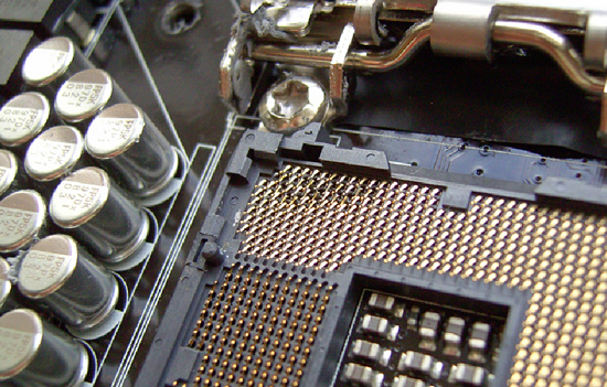
We start with a picture.
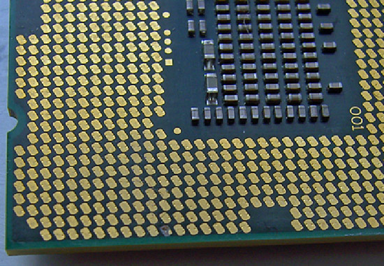
The picture above is after our Core i7 870 (LGA-1156) processor was overclocked up to 5.19GHz using our cascade with a -102° Celsius evaporator head temperature under full-load. Processor VCC power draw at these frequencies is around 160W (this is possible only due to subzero cooling), as measured with a clamp meter installed at the 12V EPS power lead. Study the pictures closely and you should notice something peculiar. Keep in mind it comes from a CPU installed in the same type of socket from a particular manufacturer.
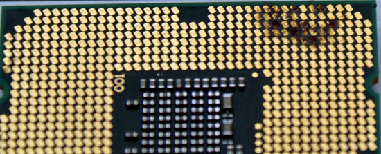
What happens after several extreme benchmark runs...
If you noticed something weird in the pictures then you understand the title of our article. We have what seems to be a potentially serious issue with proper socket loading on several P55-based motherboards when overclocking to the limit. We are of course not the only ones experiencing the problem as several of our overclocking peers have run into the same problem.
Normally we do not worry too much about mishaps during extreme overclocking testing as they are typically caused by factors outside of the supplier’s control. The overriding concern is that we have damaged every motherboard in our possession for the P55 overclocking (extreme) shootout as well as two very expensive i7/870 processors. These problems are the cause of a single component and are repeatable. As such, we thought we would provide details on current problems and will provide an update once all of the motherboard manufacturers affected have had a chance to properly respond.
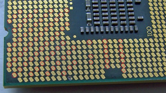
We draw your attention to the fact that the processor shown in this pictures exhibits signs of insufficient pin-to-pad contact (little to no contact) in what is a rather reproducible pattern with Foxconn manufactured 1156 sockets. As soon as an end-user mounts a CPU in a socket and latches the clamp mechanism, each pin should leave a notable mark on the associated pad.
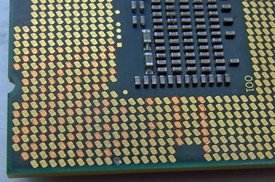
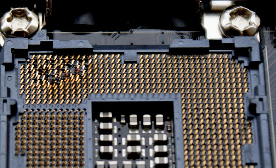
We've marked locations where this does not seem to have happened, showing what appears to be a significant reduction in the number of VCC/VSS pins for proper power delivery, and certainly not at the right load line resistance. Damage resulting from highly overclocked use in these types of situations is not solely limited to the processor; let’s take a look at what happened to some of the motherboards in which these CPU were seated.
When Intel publishes socket specifications and design tolerances, it's up to component manufacturers to strictly adhere to them when designing, manufacturing, testing and ultimately selling their "compliant" components. Of course, that's not to say Intel could not have goofed when releasing their specification, leaving out a crucial tolerance or such. It could happen, but not likely. For the time being, let's assume that's not the case; seeing as how processors installed in sockets built by other companies have exhibited no such issue in testing to date.
At first glance, one might be inclined to think LGA-1156 based processors are intolerant of high-end overclocking, almost as if by design. This is correct to some extent; a quick glance at Intel’s white papers for socket 1156 CPU’s reveals that there are around 175 pads for VCC compared to over 250 for socket 1366 CPU’s. This means socket 1156 has around 66% of the current capacity of socket 1366, the caveat being that when overclocked, processors from both platforms draw similar levels of current.
When overclocked above 4GHz, processors from both platforms will draw around 15-16 amps via the EPS 12V rail to VCC, VTT and some of the other sub –system power rails under full 8 thread load from the Intel burn test (Linx). Assuming 85% PWM efficiency, we’re looking at power draw in the region of 130-140w to VCC on both platforms. The facts point toward tighter current handling tolerances for socket 1156 when compared to socket 1366, especially when it comes to non-connection of VCC/VSS power delivery pins.
Fortunately, we think we've been able to isolate pin to pad contact issues to one particular brand of parts. Physical inspection and end-user reports all but confirm the issues only affects sockets manufactured by Foxconn at this time. The only known alternative sockets in the wild are made by LOTES or Tyco AMP. We happen to have a couple of boards from EVGA using the LOTES/Tyco AMP sockets and MSI/DFI using the LOTES socket design, and thus far those boards have been issue free given highly similar operating conditions. In fact, we’ve managed to push our LGA-1156 processors further in heavy load tests on boards made using LOTES/Tyco AMP sockets than those made with sockets from Foxconn; something we’re not putting down solely to coincidence.
So far, EVGA is the only company we know that uses sockets exclusively from LOTES on their top-tier P55 boards - for example, the EVGA P55 Classified 200, model E659. This by the way may be the onus behind the decision to market the board’s “300% More Gold Content” socket statement as a purchasing option point. If you find yourself shopping for an EVGA P55 FTW, model E657, you've got a 50/50 chance of buying one with a Tyco AMP socket design (using a LOTES backplate), as opposed to one made solely with Foxconn's, the same goes for MSI and DFI who have batches of boards in the retail channel using LOTES sockets (although we're not entirely sure on socket specifics at this point). DFI told us earlier they have dropped usage of the Foxconn sockets completely until further notice. We hear the LOTES and Tyco AMP sockets are in short supply, which is probably why Foxconn's been able to fill the void in the market with what we believe to be a lower quality alternative for the extreme overclocker.
We took one of our damaged CPU’s and inserted it into one of the EVGA (LOTES/Tyco AMP) boards and took a few pics to show contact scoring and a side by side compare to the original Foxconn socket indents.
Foxconn 1156 Socket Installation
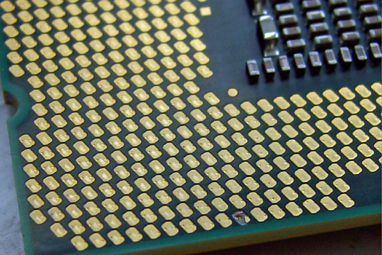
Tyco AMP / LOTES 1156 Socket Installation
Note how from a variety of angles certain pads show no evidence of contact from a Foxconn pin at all. Both the Tyco AMP and LOTES sockets have a larger pin/pad contact surface area leaving a slight scuff mark in the central area of each pad. In light of this, what we will say is that if you’re thinking of doing extreme overclocking on a board built using Foxconn's socket 1156, think again. Or, at least check your CPU for evidence of proper pin-to-pad contact.
We have not had any problems with air or water cooling overclocking up to 4.3GHz, although we do have a i5/750 that has developed a few dark pads after a thousand hours or so of constant overclocking. However, none of the boards have developed pin problems so we feel very safe in saying that any problems will probably occur only in extreme overclocking scenarios.
We also realize that partial responsibility for some of the less than acceptable CPU installations may be in fact due user installation errors. However, if users are screwing this up by doing nothing different than what they've always done when it comes to handling and installing LGA-type processors, then it's hard for us to find fault with the installer. Be aware of this situation and study the pin imprint on the CPU pads and make sure you have good contact on the VCC/VSS power delivery pads before pushing the system too hard.


273 Comments
View All Comments
Rajinder Gill - Wednesday, October 21, 2009 - link
Hi,Like you I'd like to see why it happens but cannot find anything 100% conclusive to explain it. Until it starts to happen at stock the companies in question will not respond with anything other than 'this is an overclocked issue and the socket is qualified for use'. Some tech depts are telling users they have never even heard of the problems (i've had some emails referred to me with responses). That element aside, the answer from vendors is always that it's an extreme overclocking issue if at all. Onyl thing I can tell you is that I've not had a single burnout on the other vendor sockets thus far. I don't know if that helps you, but it is the only real information I have at this point.
regards
Raja]
dank69 - Thursday, October 22, 2009 - link
I'm not sure you answered JDD's question. What do they say about pins not making contact?I just bought a 920 and an evga x58 SLI with a foxconn socket. after reading this article, I checked my cpu for pin contact. There are a few pads that show no signs of contact and others that look like they have 2 points of contact despite the fact that I only inserted the chip one time. Are there any reports of 1366 foxconns having the same contact problems?
dahwang - Wednesday, October 21, 2009 - link
When more than half of these boards claim to support overclocking, such as building in unique features that could otherwise have no other use than overclocking, the vendors cannot just simply wipe their hands of this mess. Claiming that it is an "overclocking" issue, is simply a refusal to take responsibility for a flaw in their feature-set and design.The P55-GD80 even has an "OC Genie" which is a one button overclock. Does that mean that this feature is pretty much useless? If the vendors are not going to support OC, then they really need to stop marketing about it.
I doubt any car company could install a gun in a car, but tell consumers not to use it, because it's not a supported feature and would void their warranty. It wouldn't fly at all and I think a civil jury would agree. Unless these vendors start taking a pro-active stance in resolving this issue, I foresee a class action civil suit that will end up costing them more fixing the problem.
SixOfSeven - Wednesday, October 21, 2009 - link
A better analogy might be, you drive your car 40 mph over the speed limit, the engine explodes, and the manufacturer refuses to honor the warranty. (On the other hand, if it's 400 mph over the speed limit, they may have a point.)xanonwk - Tuesday, October 20, 2009 - link
What is the board revision of the ASUS P7T55D Deluxe burnt out? I wonder if my P7P55D's board revision is same as the one Raji tested.Porksmuggler - Tuesday, October 20, 2009 - link
Clagmaster, seriously, I read your "facts" and observations a few pages back, and you have no idea what you are talking about. Here's a fact, I opened a sealed i5-750, and guess what, the pads were completely untouched, no testing marks at all. I'll freely admit my particular board with a Foxconn socket does not have the issue, but that's no reason to claim any absolutes. Then I read your last comment about power draw, are you kidding? You claim a masters in nuclear/electrical engineering and 30 years experience...you need to consider retiring.ClagMaster - Tuesday, October 20, 2009 - link
Seriously, my Q6600 has the same dimple marks the photos in the above article has. Since this is a new, factory sealed CPU I can only conclude these must be from pins from factory testing machine. The actual LGA-775 socket has pins which are rounded on top, rather than points where high voltages can concentrate to cause arcing. So I have difficulties accepting the dimples as an indication of the prescence or lack of socket pin contact.As far as power draw, I realized from the P55 schematics that the PCI-E x16 sockets and memory are controlled through the Lynnfield CPU. In the LGA-775 socketed motherboards the Northbridge contains the PCI-E and memory controllers. So for LGA-775 sockets, only the power to operate the CPU is passed through. I was just pondering, since I do not know where to find the detailed engineering information, whether the PCI-E controllers also route the 150W of power through the CPU/LGA-1156 socket to partially power the graphics cards.
I do not know the facts of this matter but I would like to have this question answered by people more knowledgeable than me. I suspect that the PCI-E signal leads do (which have some current associated with them) but the power leads bypass the CPU socket and come from the power supply.
If this is true, there is a lot more current going through LGA-1156 than LGA-775 or LGA-1366 and would go a long way in explaining the melted pins.
Yes, its true the i5-750 has a TDP of 95W. What I am questioning though is whether more power (than 95W) is being passed through the LGA-1156 socket than is presently understood by this community.
BTW -- I would love to retire and spend the rest of my years hiking, hunting, competitive shooting, cross-country sking, and building computers.
Later
Porksmuggler - Tuesday, October 20, 2009 - link
I'm not inclined to do your homework for you, but just so you know, Intel's electrical, thermal, and mechanical design specifications are readily available. The pins have well documented mechanical specs. The lands on the sealed i5-750s I have opened are untouched, and once installed do have marks that indicate pin contact. Your speculations on power draw are incorrect. Also the TDP of 95W does not represent maximum power, it is the thermal solution design target. Many in this community presently understand this, as does Intel, Document Number:322167-002. I'm glad you are looking forward to retiring. It's interesting to see someone post their political/social beliefs(pg. 14), education/work experience(pg. 16), and hobbies all in one article commentary :)ClagMaster - Wednesday, October 21, 2009 - link
I would not think of you doing my homework. But I do appreciate a useful tip on where to look.I will take a look at these specifications(obviously in the Intel website). It's a question of availability of time and I have more pressing matters to attend.
I am not adverse to posting opinions and questions even if they later prove to be wrong or foolish. I am not adverse to risk like a certain nation is. At least its simulating thoughts in others. Thomas Edison (a great experimentalist) said that for each success he had to experience 10000 failures. You learn more from the failures than the successes.
ClagMaster - Tuesday, October 20, 2009 - link
I was contemplating differences between the LGA-775 and LGA-1156 sockets and realized the LGA-775 has accommodated much greater loads without failure during extreme overclocking than the LGA-1156.Then something occurred to me.
Since the i5/i7 Lynnfields have the PCI-E controller built in, that means an extra 150W has to go through the LGA-1156 socket, through the PCI-E controller on the i5/i7 die, to the PCI-E x16 sockets. That means simply considering the 95W load of the i5/i7 CPU is only a fraction of the energy passing through this socket. the problem. So for normal operation with I can have up to 95W + 150W or 245W actually going through this socket. This is a lot of power (current) going through this socket.
Raja, it this true? Of course a graphics card or two will have seperate PCIe 6pin sockets for plugs from the power supply. But still, there is going to be a lot of current going trough this socket.
If this is true, that the LGA-1156 sockets are passing the PCI-E power as well as CPU and memory power, then no wonder these sockets are starting to fail during high overclocks.
I am starting to question whether the LGA-1156 is appropriate for serious gaming rigs which have dual SLI graphics cards.