AnandTech Power Supply Test Methodology
by Christoph Katzer on July 12, 2007 12:00 AM EST- Posted in
- Cases/Cooling/PSUs
The Testing Environment
There is one flaw in testing power supplies with programmable loads and while trying to test the sound pressure levels at the same time. Because the programmable loads get very loud there is no chance to even hear the power supply on the test stand. In order to make accurate measurements of the noise levels we needed a way to separate the test unit and the programmable loads. Our solution was to build a very thick box around the unit.
We concluded that a five-layer box with a total thickness of 6" (15cm) containing two layers of wood and three layers or special foam would suffice. It is designed as a box within a box. The inner box does not touch any part of the outer box, making it difficult for acoustic noise to pass through in the form of vibration. Each box is isolated on both sides with a layer of heavy foam which is normally used to isolate engines. In the inside we have an additional layer of 4" (10cm) thick pyramidal foam on every side of the box to eliminate the acoustic waves coming from the test object.
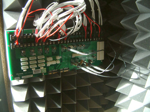
To have a completely closed system we installed the printed circuit board to which the connectors of the power supply will be attached inside the anechoic room/box. In other box designs you would need to put all the cables through the wall. Unfortunately that would result in the inside of the box not being totally isolated anymore. Our design keeps everything which needs to be connected inside of the box and maintains isolation.
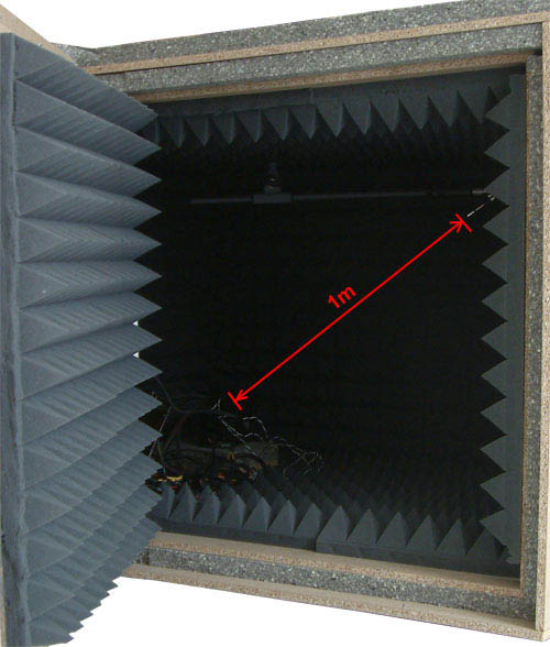
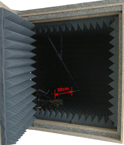
The microphone hangs on a movable stand which is connected to the roof of the box. With this we can move the microphone around in the box to the position of choice. We measure each unit from two different positions. The first is from 1m distance in conformity with normal measurements. The second position is 30cm in front of the power supply at an angle where the airflow does not interfere with the actual noise measurements.
There is one flaw in testing power supplies with programmable loads and while trying to test the sound pressure levels at the same time. Because the programmable loads get very loud there is no chance to even hear the power supply on the test stand. In order to make accurate measurements of the noise levels we needed a way to separate the test unit and the programmable loads. Our solution was to build a very thick box around the unit.
We concluded that a five-layer box with a total thickness of 6" (15cm) containing two layers of wood and three layers or special foam would suffice. It is designed as a box within a box. The inner box does not touch any part of the outer box, making it difficult for acoustic noise to pass through in the form of vibration. Each box is isolated on both sides with a layer of heavy foam which is normally used to isolate engines. In the inside we have an additional layer of 4" (10cm) thick pyramidal foam on every side of the box to eliminate the acoustic waves coming from the test object.
To have a completely closed system we installed the printed circuit board to which the connectors of the power supply will be attached inside the anechoic room/box. In other box designs you would need to put all the cables through the wall. Unfortunately that would result in the inside of the box not being totally isolated anymore. Our design keeps everything which needs to be connected inside of the box and maintains isolation.
The microphone hangs on a movable stand which is connected to the roof of the box. With this we can move the microphone around in the box to the position of choice. We measure each unit from two different positions. The first is from 1m distance in conformity with normal measurements. The second position is 30cm in front of the power supply at an angle where the airflow does not interfere with the actual noise measurements.


49 Comments
View All Comments
jtleon - Thursday, July 12, 2007 - link
For the most accurate sound level testing, the air temperature around the microphone and the power supply is very VERY important. The microphone must reach steady state temperature and be calibrated at that temperature. The air temperature in the anechoic chamber must be maintained as constant, otherwise the microphone measurements will be off as much as 3-4dB in my experience for a temp delta of only 15°F.Also, no one is interested in the noise PS generates inside the PC case, rather the noise emitted to the exterior of the PC. And beware the air temperature inside the PC is much much higher than the interior PC air temperature. I don't see how your test approach will address these critical issues.
jtleon - Thursday, July 12, 2007 - link
Ooops...I meant to say,And beware the air temperature inside the PC is much much higher than the exterior PC air temperature.
LTG - Thursday, July 12, 2007 - link
This is exactly the high bar I expected from AT and I'm really glad to see you guys do it right.I've always felt that other review sites were missing a lot in this area.
LTG
lsman - Thursday, July 12, 2007 - link
Thanks, looking forward for the reviews. Please don't let it delay (or MIA) like those m-atx or motherboard.It will be more interesting than all those HSF reviews...
Kensei - Thursday, July 12, 2007 - link
A small nitpick... Japan is also 120VAC (actually 100) and uses flat blade plugs. I live in Japan and everthing I brought here from the US works fine. See
http://www.kropla.com/electric2.htm
Martimus - Thursday, July 12, 2007 - link
I used to test power sources and signal sources for variaous automotive components, and I am wondering why you are using a multimeter to measure the output instead of an oscilliscope. You can measure both current and voltage and actually capture the waveform to measure the ripple voltage with a good o-scope. When it comes to analyzing signals, the oscilliscope is a far more valuable tool than a multimeter.just my 2 cents.
acronos - Thursday, July 12, 2007 - link
I'm interested in how the power supply handles electrical noise from the power company. I know most of us have battery backups, but the power supply should do power line noise suppression too. In my area we have brownouts (low voltage), spikes (lightning strikes nearby), and just general noise. I also use computers in a manufacturing environment, which causes significant noise on the power lines.LoneWolf15 - Thursday, July 12, 2007 - link
What you want then, are line conditioners, or a UPS with line-conditioning capability.The most a power supply provides is Active Power Factor Correction, which will clean up things a little, but that's not a subsitute for a UPS with line conditioning, which will solve your issues with brownouts and spikes. This kind of gear would be expensive and bulky to try and add into a power supply; I don't see it happening any time soon.
LoneWolf15 - Thursday, July 12, 2007 - link
Clarification: Not every PSU has Active PFC --a better explanation can be found here:http://www.dansdata.com/gz028.htm">http://www.dansdata.com/gz028.htm
sprockkets - Saturday, July 14, 2007 - link
Yeah very good explanation. Another way of looking at it is I found a site sometime ago that showed the pfc as a 90 triangle to show the relationship.I'm looking for a good test of those fanless power supplies, but again, without a fan it does put a damper in the cooling.