The GIGABYTE X570 Aorus Xtreme Motherboard Review: Fanless AM4
by Gavin Bonshor on September 24, 2019 9:00 AM ESTPower Delivery Thermal Analysis
One of the most requested elements of our motherboard reviews revolves around the power delivery and its componentry. Aside from the quality of the components and its capability for overclocking to push out higher clock speeds which in turn improves performance, is the thermal capability of the cooling solutions implemented by manufacturers. While almost always fine for users running processors at default settings, the cooling capability of the VRMs isn't something that users should worry too much about, but for those looking to squeeze out extra performance from the CPU via overclocking, this puts extra pressure on the power delivery and in turn, generates extra heat. This is why more premium models often include heatsinks on its models with better cooling designs, heftier chunks of metal, and in some cases, even with water blocks such as the ASUS ROG Crosshair VIII Formula.
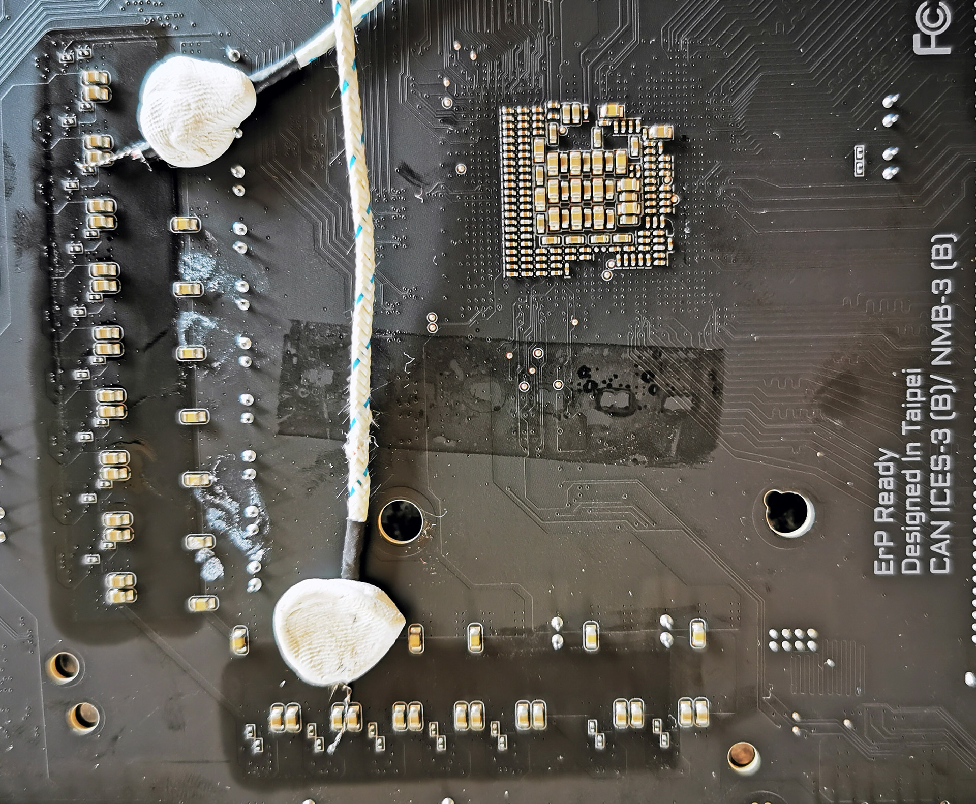
Two K-Type Thermal Probes attached to the rear of the power delivery on the GIGABYTE X570 Aorus Xtreme
Testing Methodology
Out method of testing out if the power delivery and its heatsink are effective at dissipating heat, is by running an intensely heavy CPU workload for a prolonged method of time. We apply an overclock which is deemed safe and at the maximum that the silicon on our AMD Ryzen 7 3700X processor allows. We then run the Prime95 with AVX2 enabled under a torture test for an hour at the maximum stable overclock we can which puts insane pressure on the processor. We collect our data via three different methods which include the following:
- Taking a thermal image from a birds-eye view after an hour with a Flir Pro thermal imaging camera
- Securing two probes on to the rear of the PCB, right underneath CPU VCore section of the power delivery for better parity in case a probe reports a faulty reading
- Taking a reading of the VRM temperature from the sensor reading within the HWInfo monitoring application
The reason for using three different methods is that some sensors can read inaccurate temperatures, which can give very erratic results for users looking to gauge whether an overclock is too much pressure for the power delivery handle. With using a probe on the rear, it can also show the efficiency of the power stages and heatsinks as a wide margin between the probe and sensor temperature can show that the heatsink is dissipating heat and that the design is working, or that the internal sensor is massively wrong. To ensure our probe was accurate before testing, I binned 10 and selected the most accurate (within 1c of the actual temperature) for better parity in our testing.
For thermal image, we use a Flir One camera as it gives a good indication of where the heat is generated around the socket area, as some designs use different configurations and an evenly spread power delivery with good components will usually generate less heat. Manufacturers who use inefficient heatsinks and cheap out on power delivery components should run hotter than those who have invested. Of course, a $700 flagship motherboard is likely to outperform a cheaper $100 model under the same testing conditions, but it is still worth testing to see which vendors are doing things correctly.
Thermal Analysis Results
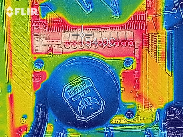
We measured 54°C on the hottest part of the power delivery, the inductors.
The GIGABYTE X570 Aorus Xtreme is using a 16-phase power delivery running in a 14+2 configuration. The CPU section is running fourteen TDA21472 70 A power stages, with two TDA21472 70 A power stages dedicated to the boards SoC. This is being controlled by the new Infineon XDPE132G5C 16-phase digital PWM controller and it's a serious bit of kit. Unlike other models in the X570 product stack which rely on a lesser phase count or doublers, GIGABYTE claims the true 16-phases to be 4% more efficient when compared to other designs. Although the power delivery is usually aimed at extreme overclockers who frequently push components to the limits for world record attempts, the design on the X570 Aorus Xtreme looks to aim at reducing heat, inefficient power loss, and for an overall more stable experience. The cooling solution on the GIGABYTE X570 Aorus Xtreme is noticeable throughout the entirety of the board with thermal reactive armor on the front, a nanocarbon coated backplate, and as we're focusing on here, the large and robust aluminium finned power delivery heatsink.

As it currently stands, the GIGABYTE X570 Aorus Xtreme includes the best power delivery of any X570 motherboard we have seen so far in our testing. With the quality of the power delivery being an increasingly popular aspect in which users make a buying decision, and especially on an overclocking friendly platform such as AM4, vendors need to get this right. In the case of the X570 Aorus Xtreme, GIGABYTE's true 14-phase design for the CPU section is cooled by a very nice aluminium finned heatsink which when our Ryzen 7 3700X is at full load at 1.475 V on the CPU VCore and with a core clock speed of 4.1 GHz, the temperatures speak for themselves. The integrated sensor within the power delivery itself monitored a maximum temperature of 49°C, with our thermal probe hitting around 44°C. While it was slightly cooler in the testing room than with other boards due to a change in weather, the results conclude that the GIGABYTE X570 Aorus Xtreme is the real deal. Using our FLIR thermal imaging camera, the hottest part of the power delivery was the inductors which measured at 54°C; for what it's worth, these aren't covered by a heatsink and cooling these comes directly from passive airflow.


42 Comments
View All Comments
Smell This - Tuesday, September 24, 2019 - link
Maybe __ but I'm not sure I get your point.A conventional top down plugin has to bend 180-degrees to route under the tray as opposed to a 90-degree 'bend' ??
DanNeely - Tuesday, September 24, 2019 - link
A 90* plug doesn't get you anything unless you're routing the cable on the same side as the board (which isn't normal these days outside of SFF), or can make a tight 90* bend as the cable comes out of the routing hole. Unless you have a really flexible cable you're not going to be able to do that. Instead you end up having to make a 270* loop (up, then forward into where drive bays used to be, and then down and back to the board), so you still end up with a big loop.With a big loop a 180* can be done without putting any bending stress on the plug. A 270* either needs more cable to match the same bending radius or will have to be tighter and puts more stress on the board as a result. With the one system I had this sort of setup in there wasn't enough slack in the cable to do a loop with enough slack that it wasn't trying to bend/twist the board up. When I plugged the cable in before the board was screwed down it was flexing the board up when I tried screwing it down on the edge with the socket. With the board screwed down first, it was very difficult to get the plug to the socket partly because of the tray meaning I could only grip the cable from one side and partly because the cable didn't want to be bent tightly enough to go in. On the whole it was among the most frustrating build steps I ever did and the stiffness of the cable meant that it completely failed at the notional goal of keeping the wires out of the way that's normally behind 90* edge plugs.
My initial thought was that a rigid 90* adapter that extended out to the cable management hole would avoid the problem by removing the need to tightly bend the cable to fit. Thinking a bit more, that probably wouldn't be enough because making a tight bend behind the board would be just as difficult; you'd either need a 180* piece so the cable could stay flat on the backside of the board, or a short extension with all loose wires to make it work.
Ratman6161 - Tuesday, September 24, 2019 - link
How about this:https://www.newegg.com/cooler-master-cma-cemb00xxb...
Ratman6161 - Tuesday, September 24, 2019 - link
https://www.google.com/search?q=ATX+24+Pin+90%C2%B...MamiyaOtaru - Wednesday, October 9, 2019 - link
cool, connect that to the side plug and come at it from behind /seek2121 - Tuesday, September 24, 2019 - link
IMO we need a better solution for all the connectors that exist on motherboards. For example, those USB3 connectors. How many times have I bent a pin trying to plug one in when it accidentally gets pulled out? More than I'd care to admit. I mean hell, at least put a snap/latch on it similar to what most SATA cables have. Ideally, we've had 1 cable running from the case to the motherboard, and 1 cable running from the PSU to the motherboard. Both connectors would had the little snap or latch or whatever you call it, and both would be right angled so that they can easily be hidden from view for a nice clean look.DanNeely - Wednesday, September 25, 2019 - link
USB-C does use a smaller and more robust connector than USB 3.0 (you can see one on this board near the diagnostic code display) that appears to take its design inspiration from PCIe.A single cable from the PSU to the mobo would run into one size fits all problems and end up huge, ex the difference between the needs of an SFF system using a 4 pin CPU header and a high end work station/gaming board using 2x8pin CPU headers and a PCIe header (to give extra power for multiple GPUs).
What could be done easily enough would be to gut the 24 pin cable by making about half of its wires optional; even if not followed up by a new smaller plug/socket a few years later it would remove a lot of the headaches from the worst connector on the mobo. This could be done safely because the original 20 pin connector dates back to when the CPU ran on 3.3v, everything else ran on 5V, and hardly anything needed 12V; vs today when 5V is used almost exclusively for USB, 3.3V for odds and ends (eg 10 of the 25/75W a PCIe card can draw from the mobo is 3.3v not 12v), while everything else runs 12V to component specific voltage regulators.
The reason nothing's happened is more or less the same as why the mess of jumper style headers for the front panel has never been replaced by a standard block style connection. The PC industry as a whole no longer cares about desktops enough to expend the effort needed for a major new standardization round. Big OEMs can and do address the issues via proprietary components scoring spare part lockin as a bonus; while for everyone else (eg the people who make parts for customer built systems/boutique vendors) the upfront time spent and short term costs from needing to bundle legacy/modern adapters for a few years is too high to try and push something on their own. Residual trauma from the effort spent on the failed BTX standard some years back was probably an issue back when desktops were still important enough of a market segment to get serious engineering effort in standard modernization as well.
Dug - Monday, October 7, 2019 - link
I just have to chime in and agree with changing the entire layout. Look what oem's can do when they aren't tied to the ancient atx power supply and standard pin layout. Look at the power supply used on an imac pro. That's how it should be done. These giant cables and connectors are really unnecessary.4everalone - Tuesday, September 24, 2019 - link
I wish MB makers would start providing SFP+ ports instead of 10GBASE-T ports. That way we at-least have the option of running fiber/copper.TheinsanegamerN - Tuesday, September 24, 2019 - link
I like the look of the board and passive X570 cooling, but am dissapointed at the lack of expansion slots. No USB 3 header? Really? Just a gen 2 that cant be used on the vast majority of cases, and even if it can it will onyl feed a singular port? No PCIe x1 slots for, say, a USB 3 header card to make up for the lack of internal headers?Granted, this is a subjective problem, not many people use more then 1-2 slots, but for the price, I would want way mroe expansion for future upgrades. Think USB 3 headers, replacement NIC or sound cards in case of on board failure, NVMe cards for RAID arrays and better cooling, ece.