MSI X48 Platinum: Four PCI Express x16 Slots to go Please....
by Kris Boughton on January 31, 2008 7:15 AM EST- Posted in
- Motherboards
Board Features and Layout
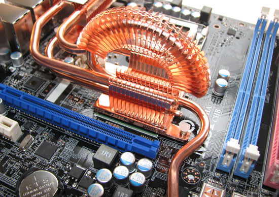
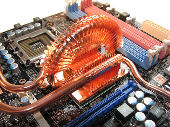
MSI's "Circupipe" Northbridge heatsink design will make yet another appearance, this time atop an X48 MCH. Our past experience with this particular cooling implementation left us thinking aesthetics must have been a bigger concern for MSI's thermal engineers than performance. Once again, we cannot help but feel as though form has been improperly placed ahead of function. We believe this may be the reason the board is somewhat resistant to maintaining stable operation with an MCH voltage above 1.4V. In addition, we would really like to see MSI take advantage of the through-hole mounting they have built into the X48 Platinum - the plastic pushpins and thin springs used for mounting the Circupipe are nowhere near capable of providing sufficient pressure to support optimal heat transfer. In summary, we applaud the use of copper and high-quality heat pipes for wicking heat from the MCH, but it's not hard to identify a few simple things that MSI could do to make overall thermal performance a lot better. In any case, we would almost always recommend replacing the thermal interface material (TIM) with some of your favorite thermal compound and this time is no different.
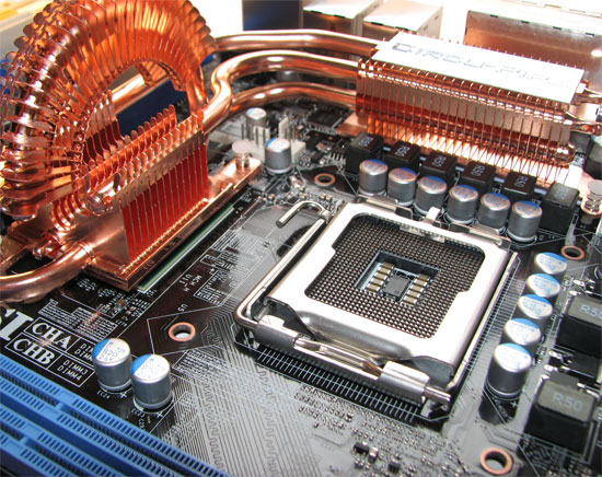
The X48 Platinum makes use of a VRM 11.1 compliant PWM (pulse-width modulator) IC from Intersil and an 8-phase power delivery design. We had no problems supplying our QX9650 processor with the power needed for stable 4GHz operation. The solid capacitors and beefy inductors used on the board scream quality - MSI has done an excellent job selecting superior components for use in this board's power circuit. Given a choice, we always prefer the application of engineering effort which focuses on design decisions that result in credible improvements over marketing hype and the extravagant use of worthless feature sets. There is a big difference between producing a well-balanced platform and one which attempts to offer too much.
We also found that the high-side MOSFETS stayed quite cool even under heavy load. In fact, we have noticed that vendors that use MOSFETS based on the older, larger body packages in general deliver boards that run much cooler in this respect. A manufacturer's decision to move to the smaller package is mainly influenced by the need for a smaller form factor with a footprint that allows them to pack more MOSFETS into an equivalent space. In turn, not only does this increase the circuit's overall power density but it also negatively impacts each component's ability to efficiently dissipate conversion losses to the surrounding environment - the result of which is a hotter running system.
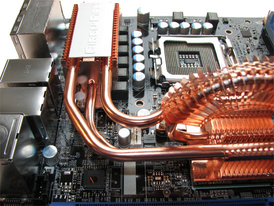
For this reason, it is not uncommon for some users to believe that heatsinks attached to the MOSFETS are located where they are for the principle purpose of cooling these components. In actuality, this is rarely the case. A lot of the time this turns out to be a good place to position additional masses of copper and aluminum, and these are thermally coupled to the MCH (and sometimes the Southbridge) through one or more heatpipes. MOSFETS are generally capable of withstanding extremely elevated operating temperatures and additional cooling often provides little to no actual benefit. For this reason we urge you to ignore any fault you may have found with MSI for not covering the MOSFETS along the top edge of the board.
One small detail that we really appreciated was the decision to reinforce the CPU heatsink mounting holes with rings of strengthening material. Little improvements such as these serve to consistently remind us of MSI's new commitment to detail. The area around the CPU socket is well clear of interference, meaning the installation of even the most massive air cooling solutions should not be a problem. The fan headers for the CPU and any fan connected to the back of our case were a little oddly positioned - be sure to seat these first before mounting your heatsink if you plan to use a large HSF.
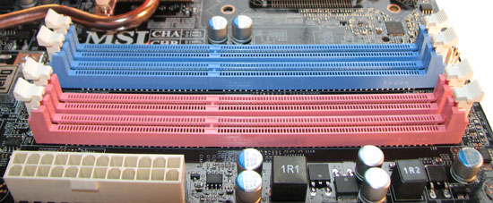
While pink and light blue certainly would not be our first choice or any choice in colors, colors aren't usually a major problem if the board performs well. Where we do find actual fault with MSI's choice in color coding is the memory slots. Traditionally, same colored slots are used to indicate the appropriate installation locations when running a kit of dual-channel memory. MSI has instead chosen to segment the slots by color based on which channel they belong to (pink being Channel A and light blue being Channel B). In the end this matters very little as long as the user understand where the modules should be placed. Which ones are the right ones, you may ask? We found our greatest overclocking was accomplished when using Slot 2 of Channel A and Slot 2 of Channel B.


21 Comments
View All Comments
HotBBQ - Thursday, January 31, 2008 - link
You cannot directly compare CAS latency across DDR revisions."Consider the latency ratings of the three most recent memory formats: Upper-midrange DDR-333 was rated at CAS 2; similar-market DDR2-667 was rated at CAS 4 and today's middle DDR3-1333 is often rated at CAS 8. Most people would be shocked to learn that these vastly different rated timings result in the same actual response time, which is specifically 12 nanoseconds." - Tomshardware
Mondoman - Friday, February 1, 2008 - link
Actually, you can compare the latency pretty directly across DDR technologies, as shown in your example. 2 clocks at DDR-333 = 4 (twice as fast) clocks at DDR2-667 = 8 (four times as fast) clocks at DDR3-1333.tayhimself - Thursday, January 31, 2008 - link
Please include stability testing. Who cares if you can get 1-5% more performance via exotic tweaks. Lets make sure that the board doesnt lock up when overclocked and laden with RAM by doing some stress testing. And make the stress testing transparent. These reviews are not as useful as or TR reviews for this reason.ATWindsor - Friday, February 1, 2008 - link
And also test if the product supports other things than graphic-cards in the PCIe-slots, a card like this begs for it.kjboughton - Thursday, January 31, 2008 - link
We will be including this type of information and much, much more in our upcoming X38/X48 motherboard round-up. As we mentioned in the review, this article is meant to provide you an early look at the layout, features, specifications, interesting BIOS options and a quick preview of any overclocking results. Stay tuned, we're confident we will address the concerns you brought to day in much more detail in just a short time.Vikendios - Thursday, January 31, 2008 - link
And please let us know how Nvidia cards work in SLI under Intel chipsets, not only under Nvidia's chipsets.I am particularly interested in twinned 8800 GT, since AnandTech called them "The only cards that matter".
OzoZoz - Thursday, January 31, 2008 - link
We all know that nVidia does not "certify" this Intel chipset to run SLI, but does that mean it won't work? I agree with Vikendios: I would like to see how SLI performs on these Intel-based motherboards.JarredWalton - Thursday, January 31, 2008 - link
I know of someone at a hardware site that was threatened with a lawsuit if they showed SLI performance on a non-NVIDIA system. (I don't know if those threats are still being sent around, but it wouldn't surprise me.) At present, the only way to make SLI work on a non-NVIDIA chipset requires a hack.Hacked drivers, but the latest drivers use some sort of encryption I believe so cracking them breaks the DMCA. I don't even know if anyone can break the encryption, and the last hacked drivers I heard about are quite old, XP only GeForce 7xxx or earlier only, and probably won't work with many modern games.
The other approach that might work would be to hack your BIOS so that it identifies itself as an nForce chipset. I don't know exactly what would be required for the ID string, or if it would work properly afterwards.
Note that SLI works on stuff like SkullTrail and PM945 (i.e. http://www.anandtech.com/mobile/showdoc.aspx?i=307...">in my Alienware m9750 review) because there's an nForce 100 bridge chip in use. nForce 100 is the precursor to the nForce 200 that's used to provide 780i with dual PCI-E 2.0 slots.
SoBizarre - Thursday, January 31, 2008 - link
It seems that the author of this article is very much “into” memory stuff. I have a little suggestion. Why don't you consider writing kind of “Everything about motherboards & RAM” guide. You could cover some practical aspects which are NEVER addressed by reviewers. For example: On motherboard supporting up to 8GB of RAM (like the one reviewed today), what is the limiting factor for RAM amount? Is it electrical(?) design of PCB, or is the address space limitation of chipset (BIOS)? Because if the BIOS can not address more than 8GB of memory, memory remapping will not help and you just can't have 8GB of RAM available to your (64bit) OS. Is that the case? Personally I don't run Virtual Machines nor do I have other reasons for installing 8GB of RAM , but other people do. Besides, it would be nice to just KNOW.smeister - Friday, February 1, 2008 - link
What's with the memory reference voltage?On the specification page (pg 2)
Memory Reference Voltage Auto, 0.90V ~ 1.25V
It should be half the DDR3 memory voltage
1.5V x 0.5 = 0.75V, so should be: Auto, 0.75V ~ 1.25V