Gigabyte GA-6RX Apollo Pro266 ATX
by Mike Andrawes on March 8, 2001 2:15 AM EST- Posted in
- Motherboards
The Layout
The GA-6RX uses quite a large PCB, measuring in at 12 by 9.5 inches; but Gigabyte did not waste any space as they put in a lot of features on the motherboard, making the layout quite "busy" with traces flying everywhere on the topmost visible layer.
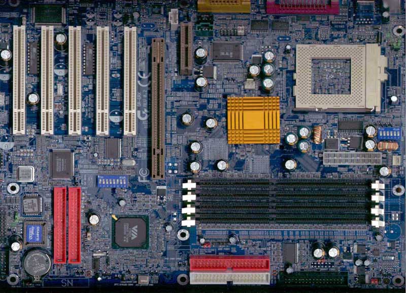
In general the layout of the board is decent, but as usual, when you try to squeeze more and more features on a board there are tradeoffs that are made. The first gripe being that the CPU's socket is placed far in the back right corner of the motherboard. As we have discussed several times in previous articles, a potential problem of this placement resides with installing or removing your CPU. Since removing the heatsink/fan unit off the socket usually requires the use of a screwdriver (to give you the leverage necessary to unmount the unit), the socket being too close to the power supply in your case may mean that installing/removing a CPU while the motherboard is mounted in the case may be a bit of an ordeal.
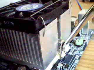
The CPU socket is too close to the right edge of the board
To make up for that potential inconvenience, Gigabyte managed to leave quite a lot of space around the CPU by having all the capacitors at least half an inch away from the socket, so you should not have any problem putting in a larger sized HSF unit for better cooling. Also, the power supply connector is placed between the socket and the DDR DIMM slots, so the power cables will not need to run over the CPU, thus making sure that the airflow around the CPU remains unrestricted.
The four DDR DIMM banks are carefully placed so that the AGP Pro slot does not block the clips at the end of the banks. While this isn't a reason to run out and praise the board, it is good to know that Gigabyte does take these types of issues into consideration.
The two IDE and one floppy connector, powered by the VT8233 South Bridge are located on the bottom of the motherboard, which means they will be very close to the drive bays when everything is in the chassis.
Unfortunately, the third and fourth IDE connectors supported by the Promise IDE controller are located vertically below the third PCI slot. Not only does that block the use of any full length PCI cards on the third PCI slot, but since the 80-pin Ultra ATA 66/100 cables have a certain limit on their length, that means you might not be able to put drives too high in your case if you want to connect them to the two ATA/100 channels.


0 Comments
View All Comments