Streacom's FC10 and Nano150: Building a Fanless Ivy Bridge HTPC
by Ganesh T S on December 22, 2012 3:30 AM EST- Posted in
- HTPC
- Fanless
- Ivy Bridge
Build Process
The FC10 chassis has limited external ports (only two USB 3.0 capable ports on the side panel other than the ODD button / power button and LED on the front panel). We don't have front panel audio, eSATA / Firewire ports or fancy LCD screens to connect to the main board. This is actually advantageous as it allows us plenty of room and resource efforts to direct towards assembling the cooling system. As we had mentioned earlier, Streacom is no newcomer to the fanless chassis bandwagon. In fact, their FC5 Evo Fanless chassis received good reviews. Unfortunately, the profile of the chassis, as well as the positioning of the screw slots for the heat pipe system meant that the choice of motherboards was extremely limited. Streacom touts extended motherboard compatibility as one of the strong points, and we were forced to test it out because of the design of the Asus P8Z77-I Deluxe motherboard.
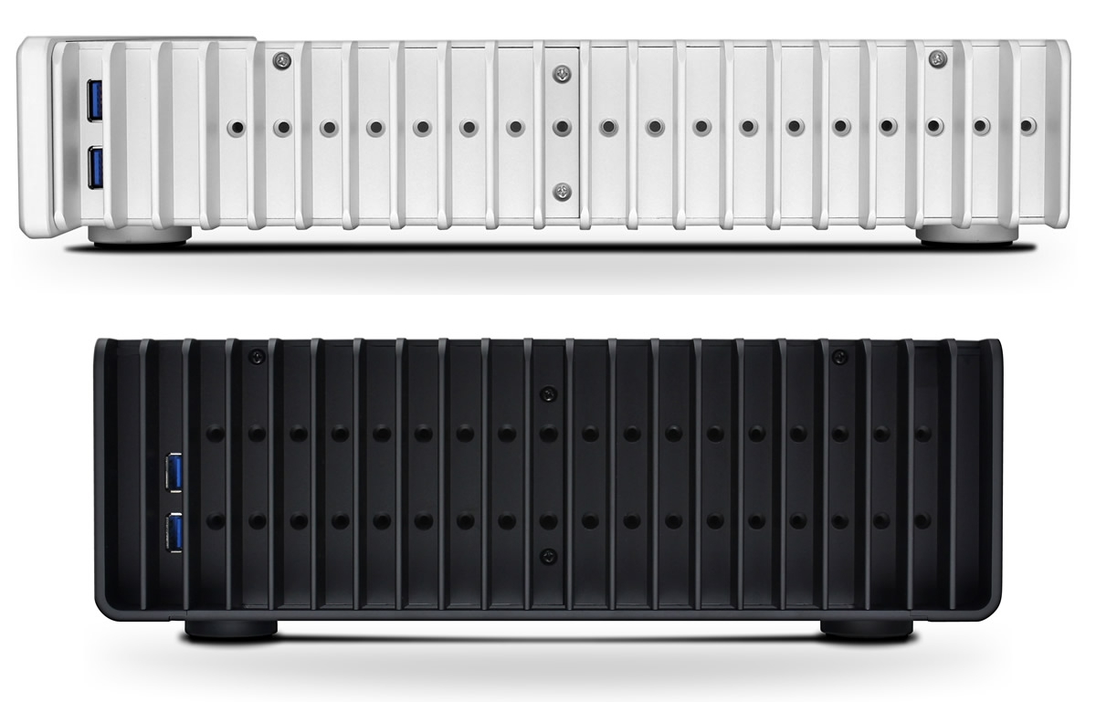
Improved Motherboard Compatibility with Dual Heat Sink Mounting Levels in the FC10 (Bottom) Compared to the FC5 (Top)
Streacom FC10 Motherboard Compatibility
Most motherboards would be served fine with the lower set of screw slots for the heat pipes, but the Digi + VRM for ITX module on the motherboard blocked the path, as evident from the photograph below.
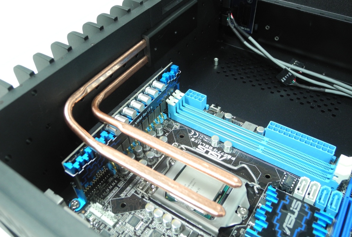
In order to raise the mounting height for the heat pipe blocks, it was necessary to use the Streacom HT4 Thermal Riser. This is a separate accessory needed only if the choice of motherboard makes it necessary. Streacom's US reseller, Perfect Home Theater delivered the HT4 to us on very short notice, and enabled us to proceed with the rest of the build.


Mounting the HT4 Riser
Streacom's website has user guides for all their products, but, unfortunately, the one uploaded for the HT4 wasn't current. Some time was lost in trying to assemble the riser following that guide, but Streacom finally came back with the updated version after we pointed out the error. The mounting process included spreading a generous dose of the supplied thermal paste on the processor and the base of the HT4 riser. The riser was then put on top of the processor. An interesting point to note here is that the contact surface between the processor and the riser is not entirely flat due to the presence of the copper heat pipes. We were a bit worried since the default assembly instructions (without the riser) indicated that the flat lower CPU mount would be placed on the processor. As we found out later, our fears were unfounded, and despite the not-so-flat riser being in contact with the processor, we had stellar thermal performance.


Streacom supplies both AMD and Intel-type upper CPU mounts. They have to manually be fitted with spring screws and are used to keep the lower part of the HT4 riser in place and in good contact with the CPU itself. After this, the heat pipes supplied with the FC10 chassis had to be arranged to align with the HT4's four copper segments. The FC10 also has thermal blocks (which have to be applied with thermal paste) into which the heat pipes have to be inserted before getting mounted on the side of the chassis (one of the segments is shown in the photograph above). After placement, the upper HT4 mount had to be fastened to the HT4 riser so as to sandwich the HT4's copper segments and the heat pipes together. It goes without saying that all points of contact had thermal paste applied liberally.


The FC10 chassis comes with a lower CPU mount (which has an appearance similar to that of the HT4 upper mount) which goes unused in the above configuration. We had unsuccessfully tried to use to the FC10 lower CPU mount instead of the HT4 upper mount (thanks to Streacom's original faulty user guide), and that explains the presence of thermal paste at unnecessary places in the above gallery. Even though it wasn't suggested, we applied thermal paste further on the upper side of the HT4 upper mount and placed the FC10's lower CPU mount on top of it.
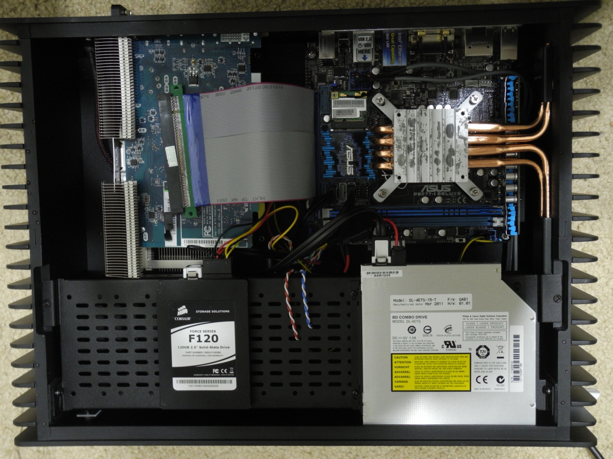
Mounting the SSD and ODD on the drive cage was fairly uneventful, except for some known issues with the ODD mounting. Since the same drive was mounted with all four screws in the ASRock HTPC drive cage, I think Streacom should pay a little bit more attention to the ODD brackets. The slimline notebook drive we used comes with a smaller SATA power connector, and we used an adapter to convert the full-size SATA power connector from the Nano150 PSU to the optical drive.
Before moving on to the thermal performance evaluation, it must be noted that we have mounted the Sapphire HD 7750 Ultimate in the PCIe slot and also connected a flexible PCIe riser to the motherboard. We wanted to test out whether the Nano150 would be able to power up such a configuration, and we were relieved to find that there were no issues. Another point to be noted is the capacitors in the Nano150 beneath the SATA data cable connected to the ODD. They abut into the space above the DIMM slot, and though we were able to fit in both the DRAM modules (with the heat sink of the DRAM module slightly scraping the capacitors), we decided to take the safe route by just installing one 4 GB DRAM module in the slot further away from the 24-pin connector.


63 Comments
View All Comments
colonelciller - Sunday, December 23, 2012 - link
Does the i3-3225 support 23.976 playback?Aikouka - Sunday, December 23, 2012 - link
Last I recall, Intel's drivers do have a "24 FPS" setting, but it is not true 23.976. However, my information may be out of date!casteve - Saturday, December 22, 2012 - link
Thanks for the review, but what are the units of time in the graphs? seconds, minutes, mayan long count?ganeshts - Saturday, December 22, 2012 - link
Apologize for the oversight. The time unit is in (s). The first graph is not very clear (I had actually let our power logger script run for 100 minutes = 6000s). For the loading temperature graphs, I had indicated in the text that the burn-in testing was run for 12 hours (=43200s).kyuu - Saturday, December 22, 2012 - link
First paragraph on page 3:"There was a toss up between building a Trinity-based testbed and a Ivy Bridge-based testbed. In the end, the fact that Trinity emerged as being a capable madVR candidate (with software based decoding), and the fact that madVR recently introduced DXVA scaling (an upside for Intel since its offerings weren't fully madVR capable earlier, and something that we wanted to test out) persuaded us to go for an Intel-based testbed."
Am I missing something or is this messed up? You describe (what I assume are) positive aspects of Trinity, then use that as the justification for using Ivy Bridge? Huh?
ElvenLemming - Saturday, December 22, 2012 - link
The way I interpreted that was that because the madVR support is newer and less-tested for Intel, they decided to go with an Intel build here so they could use the same machine for future madVR testing.The paragraph wasn't worded very clearly, but that's what I got out of it.
ganeshts - Saturday, December 22, 2012 - link
Yes, I could have conveyed that in a better manner, but ElvenLemming's interpretation is right. In our Trinity and Ivy Bridge reviews, we found that 720p60 H.264 streams gave trouble to HD 4000. Recently, madVR introducied DXVA scaling, and I have it from very reliable sources that Mathias (madVR developer) is working closely with Intel. So, we wanted to have the right platform to evaluate these developments.kyuu - Sunday, December 23, 2012 - link
Ah got it. Thanks for the clarification.Schafdog - Saturday, December 22, 2012 - link
What's the idle power of the system?ganeshts - Saturday, December 22, 2012 - link
That is coming in Part 2 of the review :) As a sneak peek, I can say it is around 28 W. Power measurement during Blu-ray playback and other workloads will be dealt with in detail in the next series installment.