Budget Micro-ATX P55 Faceoff: Gigabyte GA-P55M-UD2 and ASRock P55M Pro
by Gary Key on October 5, 2009 12:30 PM EST- Posted in
- Motherboards
Gigabyte GA-P55M-UD2 Layout
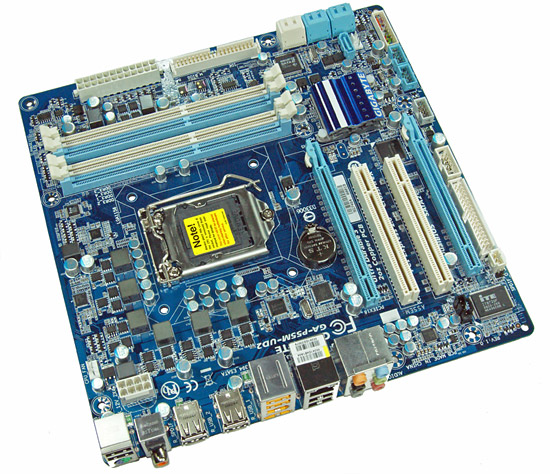
Considering the limited board space, Gigabyte did a very good job fitting all of the peripherals onto this board. About the only negatives we can think of is the continued inclusion of the floppy drive port, lack of passive cooling for the MOSFET area, and only two fan headers. The board does support CrossFireX operation although we highly recommend against this setup as the second PCIe x16 slot is actually an x4 electrical slot running off the P55 chipset with performance suffering up to 30% depending on the choice of video card and game.
The UD2 features Gigabyte's UltraDurable 3 technology that features their 2oz. copper based PCB, solid capacitors, low RDS(on) MOSFETs, and ferrite core chokes.
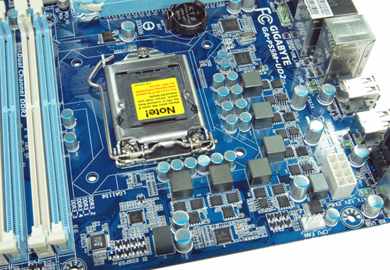
Gigabyte utilizes a high quality four-phase plus one PWM setup on this board. The CPU area is open for the most part and will accommodate larger coolers like the Thermalright Ultra 120 eXtreme. Large push/pull coolers like the Vigor Monsoon III LT will block the first DIMM slot and potentially can interfere with the first PCIe x16 slot.
We originally thought additional airflow across the MOSFETs would be required to ensure 24/7 stability when overclocking. However, the MOSFETs only reached 58.6C under full load with our i7/860 operating at 4.2GHz. We ran the board for 200 hours in with this overclock setting with the case fans turned off. This left just the Corsair 750HX providing air exhaust capabilities.
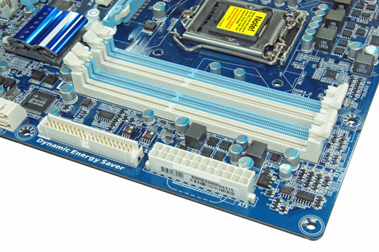
The IDE port, 24-pin ATX power connector, and the four DIMM slots are located in the lower right hand corner of the board. This board supports dual channel memory configurations and 16GB of DDR3 memory when using 4GB DIMMS. Installing the memory with a video card inserted in the first slot is difficult but not impossible.
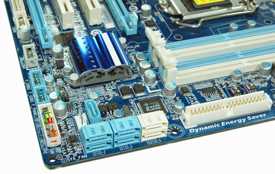
There are five (blue) SATA 3Gb/s ports provided by the P55 chipset that support RAID 0, 1, 5, 10. The sixth port available on the P55 (under the blue heatsink) is utilized on the I/O panel for eSATA. Gigabyte includes the JMicron JMB363 3Gb/s SATA chip that drives the two white SATA ports and provides IDE support. The front panel header, two USB headers, and the IEEE 1394a header are located at the edge of the board.
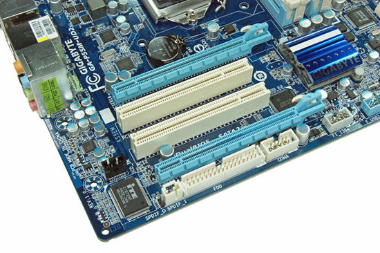
Gigabyte includes two PCIe x16 slots (x16 operation for the first slot, x4 operation for the second slot) and two PCI slots. The first PCI slot will be unavailable when utilizing a dual slot video card.
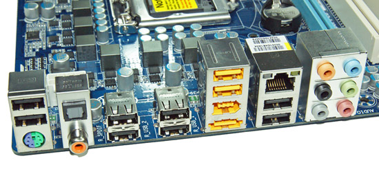
Last but not least is the I/O panel. We have ten USB 2.0 ports (total of fourteen on the board), combination PS/2 port, single eSATA port from the P55, IEEE 1394a port offered by the TI TSB43AB23 chipset, Gigabit Ethernet LAN port via the Realtek RTL8111D chipset, optical out/coaxial out S/PDIF ports, and the audio panel that provides 8-channel audio output via the Realtek ALC 888B HD audio codec.


Tech
One of the highlighted features that Gigabyte implemented in the GA-P55M-UD2 motherboard is the Ultra Durable 3 technology. Ultra Durable 3 features lower ESR solid capacitors, lower RDS(on) MOSFETs, and ferrite core chokes. Gigabyte now rates the longevity of the solid capacitors at 50,000 hours or approximately 6 years of continuous use.
The second major improvement cited by Gigabyte in their Ultra Durable 3 design is the introduction of a 2-ounce copper PCB for both the Power and Ground layers compared to the typical 1-ounce layers found in most consumer boards. Gigabyte claims this technology offers substantially lower system temperatures, superior energy efficiency, and improved overclocking. We can verify the temperature and energy efficiency claims; at least compared to other boards in this price sector at idle conditions.
DPC Latency
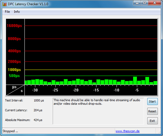
We get a lot of requests for DPC latency results on each board we test. The latency variations between manufacturers utilizing the same chipset vary more than one might imagine. In the past, Gigabyte has had problems in this area when others did not. We are happy to report that it appears those problems are thing of the past. All of our P55 boards so far have exhibited the same behavior in this benchmark. Our test used the Core i5/750 at stock settings with 8GB of memory installed with timings set to 6-6-6-18 at DDR3-1333.


55 Comments
View All Comments
Gary Key - Monday, October 5, 2009 - link
The PCIe lanes coming off the P55 are 2.0, the problem is that they are running at 1.x speeds (2.5GT/s). On these two boards, the x16 slot is off Lynnfield and will not be affected by any card placed in the x4 or x1 slots off the P55.Mr Perfect - Tuesday, October 6, 2009 - link
I should probably know this, but what does a 2.0 slot running at 1.x speed bring to the table that a 1.x slot doesn't? Does it provide more power or something?MadMan007 - Tuesday, October 6, 2009 - link
Yes I was half right with my post and nothing Gary said was technically wrong it's just misleading. They are PCIe 2.0 spec slots but running at half speed, this is clear from Intel's chipset disgram. It's really a farce to call them PCIe 2.0 though because the overridingly most important change from 1.x to 2.0 is the double bandwidth, there are other changes like the power rating I believe and maybe some low level changes but nothing major. I think it's false advertising to call them PCIe 2.0 personally because they don't fully conform to the spec.In any case I'd still like to know how many lanes the main CPU-based slot retains when a 1x or 4x card is placed in a secondary CPU-based PCIe slot. Anandtech seems to be more receptive to odd little investigations like this so I hope Gary will check it out.
james.taylor - Monday, May 10, 2010 - link
Hi Gary, Thank you so much for this informationjames.taylor - Monday, May 10, 2010 - link
again thanks but if you want to buy new memory then http://www.memoryx.net/ this can help you