Budget Micro-ATX P55 Faceoff: Gigabyte GA-P55M-UD2 and ASRock P55M Pro
by Gary Key on October 5, 2009 12:30 PM EST- Posted in
- Motherboards
Gigabyte GA-P55M-UD2 Layout
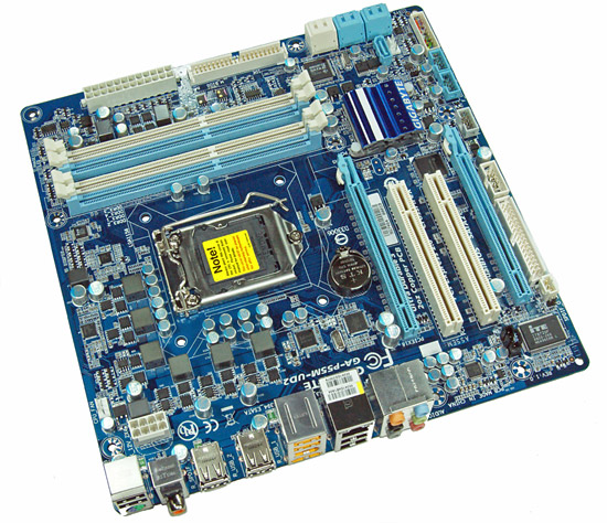
Considering the limited board space, Gigabyte did a very good job fitting all of the peripherals onto this board. About the only negatives we can think of is the continued inclusion of the floppy drive port, lack of passive cooling for the MOSFET area, and only two fan headers. The board does support CrossFireX operation although we highly recommend against this setup as the second PCIe x16 slot is actually an x4 electrical slot running off the P55 chipset with performance suffering up to 30% depending on the choice of video card and game.
The UD2 features Gigabyte's UltraDurable 3 technology that features their 2oz. copper based PCB, solid capacitors, low RDS(on) MOSFETs, and ferrite core chokes.
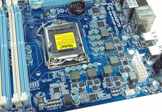
Gigabyte utilizes a high quality four-phase plus one PWM setup on this board. The CPU area is open for the most part and will accommodate larger coolers like the Thermalright Ultra 120 eXtreme. Large push/pull coolers like the Vigor Monsoon III LT will block the first DIMM slot and potentially can interfere with the first PCIe x16 slot.
We originally thought additional airflow across the MOSFETs would be required to ensure 24/7 stability when overclocking. However, the MOSFETs only reached 58.6C under full load with our i7/860 operating at 4.2GHz. We ran the board for 200 hours in with this overclock setting with the case fans turned off. This left just the Corsair 750HX providing air exhaust capabilities.
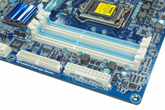
The IDE port, 24-pin ATX power connector, and the four DIMM slots are located in the lower right hand corner of the board. This board supports dual channel memory configurations and 16GB of DDR3 memory when using 4GB DIMMS. Installing the memory with a video card inserted in the first slot is difficult but not impossible.
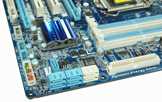
There are five (blue) SATA 3Gb/s ports provided by the P55 chipset that support RAID 0, 1, 5, 10. The sixth port available on the P55 (under the blue heatsink) is utilized on the I/O panel for eSATA. Gigabyte includes the JMicron JMB363 3Gb/s SATA chip that drives the two white SATA ports and provides IDE support. The front panel header, two USB headers, and the IEEE 1394a header are located at the edge of the board.
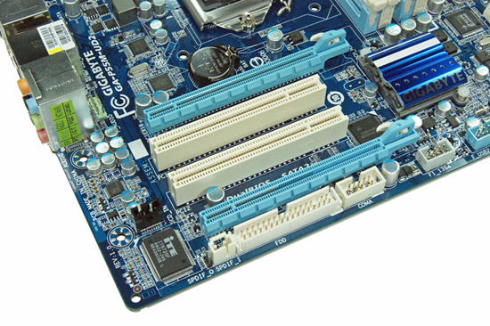
Gigabyte includes two PCIe x16 slots (x16 operation for the first slot, x4 operation for the second slot) and two PCI slots. The first PCI slot will be unavailable when utilizing a dual slot video card.
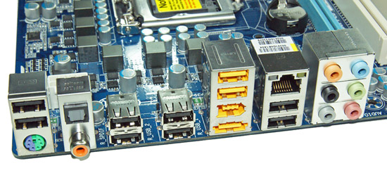
Last but not least is the I/O panel. We have ten USB 2.0 ports (total of fourteen on the board), combination PS/2 port, single eSATA port from the P55, IEEE 1394a port offered by the TI TSB43AB23 chipset, Gigabit Ethernet LAN port via the Realtek RTL8111D chipset, optical out/coaxial out S/PDIF ports, and the audio panel that provides 8-channel audio output via the Realtek ALC 888B HD audio codec.


Tech
One of the highlighted features that Gigabyte implemented in the GA-P55M-UD2 motherboard is the Ultra Durable 3 technology. Ultra Durable 3 features lower ESR solid capacitors, lower RDS(on) MOSFETs, and ferrite core chokes. Gigabyte now rates the longevity of the solid capacitors at 50,000 hours or approximately 6 years of continuous use.
The second major improvement cited by Gigabyte in their Ultra Durable 3 design is the introduction of a 2-ounce copper PCB for both the Power and Ground layers compared to the typical 1-ounce layers found in most consumer boards. Gigabyte claims this technology offers substantially lower system temperatures, superior energy efficiency, and improved overclocking. We can verify the temperature and energy efficiency claims; at least compared to other boards in this price sector at idle conditions.
DPC Latency
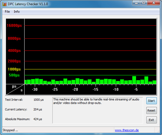
We get a lot of requests for DPC latency results on each board we test. The latency variations between manufacturers utilizing the same chipset vary more than one might imagine. In the past, Gigabyte has had problems in this area when others did not. We are happy to report that it appears those problems are thing of the past. All of our P55 boards so far have exhibited the same behavior in this benchmark. Our test used the Core i5/750 at stock settings with 8GB of memory installed with timings set to 6-6-6-18 at DDR3-1333.


55 Comments
View All Comments
goinginstyle - Monday, October 5, 2009 - link
I loved the review also and it showed a lot of work went into testing these boards. I just wonder when TA152H is going to ruin this thread but until then it nice to see constructive posts. I also wish the mobo guys would just drop the floppy and IDE ports when possible. It would free up board real estate and hopefully drop the cost a little more.papapapapapapapababy - Monday, October 5, 2009 - link
not touching any of this at least it has Socket 775 mounting holesusb3 @ pci3 @sata6 and im there.
Docket - Monday, October 5, 2009 - link
It is a shame that there are no Linux versions of the Gigabyte software reviewed here... oh well maybe some day in a distant future.mitt - Monday, October 5, 2009 - link
Hallelujah! DPC latency benchmark in AnandTech reviews!mathew7 - Monday, October 5, 2009 - link
When MB manufacturers are going to let go of PCI?I recently switched to Micro-ATX, and found I have a real problem of choosing a motherboard.
I'm looking at buying a PCIe X-Fi, but would like to use a dual-slotted video card. But I would like to keep my options open for a second card (I'm htinking about physics, not SLI/CF, so dual-slot cooling is not required). While the Gigabyte does not pass my requirements, the Asrock also has a problem: usage of a dual-slot-cooled card inhibits the usage of the PCIex1 slot.
I intend to switch to i5/P55 at the start of next year, so I'm watching closely.
Jaybus - Thursday, October 8, 2009 - link
That will be a slow transition. There are still a lot of PCI adapters being sold out there, especially for some specialty markets like scientific instrumentation that take time to transition to new interfaces due to cost and low volume. Nevertheless, the demise of PCI is starting to happen. For most people it's not a big deal, because they only need 1 or 2 PCIe x16 slots for graphics cards and will never use the rest of the slots anyway.MadMan007 - Monday, October 5, 2009 - link
Kind of funny but Intel is leading the pack in that specific area, their $200 (ugh) 'Extreme' DP55SB mATX P55 mobo has no PCI slots, also no PS/2, IDE or floppy. Maybe it's consistent since they ditched PS/2 and other legacy connectors on some boards a while back. No telling on the overclocking front but it is an 'extreme' board so it may have at elast some overclocking features. It has a couple of neat features actually, Bluetooth and Intel NIC.Jaybus - Thursday, October 8, 2009 - link
And uATX is a good platform to remove PCI from. Why not drop it from uATX? They can always leave it on ATX boards for a while for those who absolutely need PCI slots. I think other manufacturers will follow that path very soon.MadMan007 - Monday, October 5, 2009 - link
*bzzt* The only PCIe 2.0 lanes on a P55 platform are from the CPU. So look carefully at specs and double check with companies when they say their secondary slots, especially ones that aren't even 16x mechanical, are PCIe 2.0. The UD2's 4x electrical slot in particular is clearly not according to Gigabyte, the ASRock claims to be but I'm not sure how if all 16 CPU PCIe 2.0 lanes are used for the graphics slot. If they used a lane splitter to provide PCIe 2.0 lanes to the other slots it kind of defeats the purpose, and if so it would be good to check performance with those slots populated.MadMan007 - Monday, October 5, 2009 - link
To follow up on this, the comment was based on the first few paragraphs. I looked over Intel's manual for their 'extreme' mATX board for my post about it and Intel actually states their mobo has PCIe 2.0 lanes to the additional PCIe slots. Not surprising for the 8x slot I guess but it is for the 1x slots and it seems unlikely Intel would misquote specs.On a related note there is one thing I've not seen yet from any review and that is how PCIe lanes get assigned, mainly to the primary 16x slot, when populating a secondary PCIe slot with a 1x or 4x card. Do the lane splitter chips assign 8x lanes to a secondary slot which has a 1x or 4x card or what? Not a huge deal but it's a little thing that would be nice to know.