Budget Micro-ATX P55 Faceoff: Gigabyte GA-P55M-UD2 and ASRock P55M Pro
by Gary Key on October 5, 2009 12:30 PM EST- Posted in
- Motherboards
Gigabyte GA-P55M-UD2 Layout
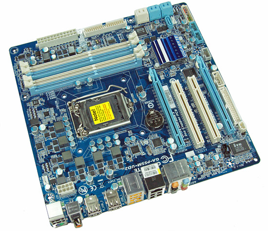
Considering the limited board space, Gigabyte did a very good job fitting all of the peripherals onto this board. About the only negatives we can think of is the continued inclusion of the floppy drive port, lack of passive cooling for the MOSFET area, and only two fan headers. The board does support CrossFireX operation although we highly recommend against this setup as the second PCIe x16 slot is actually an x4 electrical slot running off the P55 chipset with performance suffering up to 30% depending on the choice of video card and game.
The UD2 features Gigabyte's UltraDurable 3 technology that features their 2oz. copper based PCB, solid capacitors, low RDS(on) MOSFETs, and ferrite core chokes.
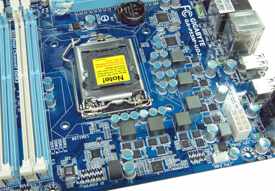
Gigabyte utilizes a high quality four-phase plus one PWM setup on this board. The CPU area is open for the most part and will accommodate larger coolers like the Thermalright Ultra 120 eXtreme. Large push/pull coolers like the Vigor Monsoon III LT will block the first DIMM slot and potentially can interfere with the first PCIe x16 slot.
We originally thought additional airflow across the MOSFETs would be required to ensure 24/7 stability when overclocking. However, the MOSFETs only reached 58.6C under full load with our i7/860 operating at 4.2GHz. We ran the board for 200 hours in with this overclock setting with the case fans turned off. This left just the Corsair 750HX providing air exhaust capabilities.
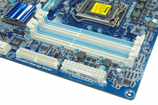
The IDE port, 24-pin ATX power connector, and the four DIMM slots are located in the lower right hand corner of the board. This board supports dual channel memory configurations and 16GB of DDR3 memory when using 4GB DIMMS. Installing the memory with a video card inserted in the first slot is difficult but not impossible.
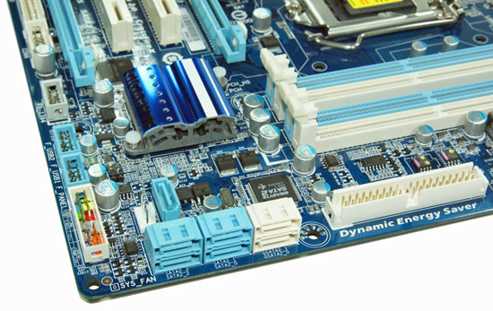
There are five (blue) SATA 3Gb/s ports provided by the P55 chipset that support RAID 0, 1, 5, 10. The sixth port available on the P55 (under the blue heatsink) is utilized on the I/O panel for eSATA. Gigabyte includes the JMicron JMB363 3Gb/s SATA chip that drives the two white SATA ports and provides IDE support. The front panel header, two USB headers, and the IEEE 1394a header are located at the edge of the board.
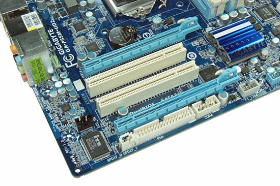
Gigabyte includes two PCIe x16 slots (x16 operation for the first slot, x4 operation for the second slot) and two PCI slots. The first PCI slot will be unavailable when utilizing a dual slot video card.
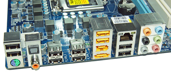
Last but not least is the I/O panel. We have ten USB 2.0 ports (total of fourteen on the board), combination PS/2 port, single eSATA port from the P55, IEEE 1394a port offered by the TI TSB43AB23 chipset, Gigabit Ethernet LAN port via the Realtek RTL8111D chipset, optical out/coaxial out S/PDIF ports, and the audio panel that provides 8-channel audio output via the Realtek ALC 888B HD audio codec.


Tech
One of the highlighted features that Gigabyte implemented in the GA-P55M-UD2 motherboard is the Ultra Durable 3 technology. Ultra Durable 3 features lower ESR solid capacitors, lower RDS(on) MOSFETs, and ferrite core chokes. Gigabyte now rates the longevity of the solid capacitors at 50,000 hours or approximately 6 years of continuous use.
The second major improvement cited by Gigabyte in their Ultra Durable 3 design is the introduction of a 2-ounce copper PCB for both the Power and Ground layers compared to the typical 1-ounce layers found in most consumer boards. Gigabyte claims this technology offers substantially lower system temperatures, superior energy efficiency, and improved overclocking. We can verify the temperature and energy efficiency claims; at least compared to other boards in this price sector at idle conditions.
DPC Latency
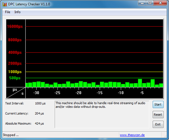
We get a lot of requests for DPC latency results on each board we test. The latency variations between manufacturers utilizing the same chipset vary more than one might imagine. In the past, Gigabyte has had problems in this area when others did not. We are happy to report that it appears those problems are thing of the past. All of our P55 boards so far have exhibited the same behavior in this benchmark. Our test used the Core i5/750 at stock settings with 8GB of memory installed with timings set to 6-6-6-18 at DDR3-1333.


55 Comments
View All Comments
yacoub - Tuesday, October 6, 2009 - link
785G is just onboard graphics halfbreed between 780 and 790 or whatever. until AMD releases a new line of high-end boards worth reviewing, why bother?haplo602 - Wednesday, October 7, 2009 - link
P55 is just half a chipset, i5 took over some of the functionality anyway ... why bother ?tommy101 - Wednesday, September 8, 2010 - link
beastyhacks79.smfnew.com the best psp hacking sitebollux78 - Tuesday, October 6, 2009 - link
Why do we need PCI anymore? I´ll tel you why: The PCI bus is more than enough for a hell bunch of applications, that´s it. If you have a damn good sound card or video capture, or whatever the card you have, and it´s PCI, you´d love to have the slot in there, because you don need to ditch that card and bet a "fantastic" PCIE x1 new card.C´mon people, let´s use the computer for the right purpose, not just to give money to the manufacturers buying new parts that you don´t
necessarily need.
I know, I´m being inflexible and oldschool, but, please, evolution is one thing, marketing is a completely different animal.
strikeback03 - Tuesday, October 6, 2009 - link
IMO it is more a board real estate problem than a case of buying the latest and greatest. On these P55 uATX boards you have 4 slots, one of which has to be devoted to graphics unless it is a headless server. If you use a dual slot graphics card (which a substantial portion of the readers on this site) you lose a second slot, and ideally you would have an open slot beneath that to ease airflow. So that leaves you with one or in a pinch two slots, therefore what interface they are is quite important. PCIe has been out on boards for what, 5-6 years now? I'd say its time to stop selling PCI cards and leave the PCI slots only on full ATX boards (plus maybe a few HTPC-oriented uATX boards) and let the interface finally die off.Though I'd say IDE has even less of a place now, SATA hard drives have been the norm for years and even optical drives for a few years. Time to upgrade if you are still carting one of those around.
sonicdeth - Monday, October 5, 2009 - link
Thanks Gary for the detailed review. Can't wait for the p55 roundup, and I'm also very interested now in your audo codec review.mindless1 - Monday, October 5, 2009 - link
... but I don't see the sense in SLI on mATX. Using the typical long video cards means you can't have a shorter depth case, just shorter height and since when is the area above your computer case a vital piece of real-estate?With 2, 8 or 16X slots onboard it only makes sense to me to go full ATX, is someone with the system budget to build a powerhouse gaming machine really poor enough, indescriminating enough, or young enough (to not have desirable cards from past systems) they don't want to add some other cards?
I hate to say it but this is getting to be a madness, the idea that we need to focus centrally on gaming ability of a board. Most people are not hard core gamers, but factually speaking, most hard core gamers don't do SLI either. Granted you can use a 16x slot for cards with fewer lanes, that seems the only saving grace for the two boards.
It's getting to the point I want a cTX case design where the drive racks are not in front of the mainboard and PSU, they are above them, so the case is even taller than std. ATX but not as deep.
Might tip over a little easier but earthquakes are rare here and plenty of other household items are more tip-happy than that would be.
strikeback03 - Monday, October 5, 2009 - link
There are cases made to hold a uATX board lying on the bottom, making it kinda a wider Shuttle. I'm personally looking for full ATX as well though, as the height doesn't matter too much to me (pretty sure anything short of a ABS Canyon or some of the bizarre decorative cases would fit under my desk) and don't want to limit my slot selection.Sunburn74 - Monday, October 5, 2009 - link
Hey Anand,Gigabyte boards have on issue that drives me nuts. As soon as you start overclocking them, you lose the ability to S3 sleep. When you do your maximal overclocks for various board reviews, would you mind testing if S3 sleep was maintained at those maximal overclocks?
Gary Key - Monday, October 5, 2009 - link
This board resumes from S3 (USB keyboard) at up to 215 Bclk (mentioned in the thoughts section, make that more visible next time) with our setup and that includes an external hard drive on the Firewire port which is properly instructed to shut down and restart.