AnandTech Power Supply Test Methodology
by Christoph Katzer on July 12, 2007 12:00 AM EST- Posted in
- Cases/Cooling/PSUs
Chroma Programmable DC Loads 6314
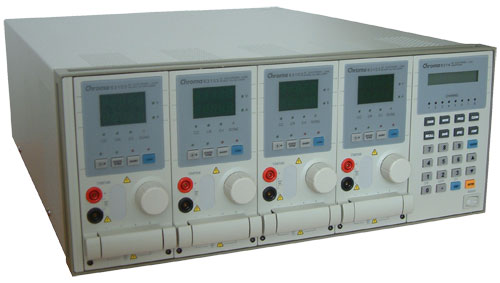
Our test equipment contains two Chroma programmable DC Loads which enable us to test power supplies with an output of up to 1500W. The biggest advantage of the Chroma DC Loads is simply the high precision it provides. It can measure differences as small as 0.001V and 0.0001Amp which will provide us with best-in-class results.
The Chroma programmable load is the heart of our equipment and controls the functions of the power supply. With it we can see the delivered voltage in response to the specific amount of load we are placing on each rail. In addition we will test security features like Over Current Protection (OCP), short circuit, and Over Power Protection (OPP).
A very important aspect in testing a power supply correctly is to put the right load on each rail. Stating that a 10% load is put on the power supply says nothing about the distribution of the load on each rail. For example, this 10% could be 80% load on the +12V1, 5% on +12V2 and +12V3, and 3% on +12V4; the rest would be on the other rails. In other words, simply giving a single all-encompassing load rating means that the load can be put on each rail differently, as long as the total load is always 10%. This is not a correct test according to the Intel Design Guide.
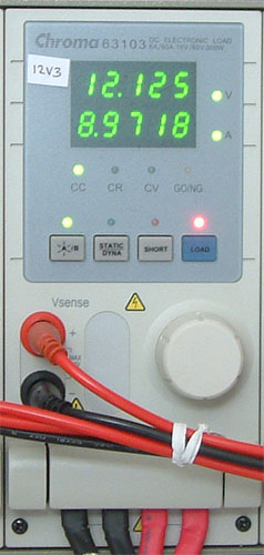
The guide clearly states how the percentages of loads need to be distributed on each rail, and we are working strictly according to this specification. It is not unusual to get an odd looking number since our calculations are strictly mathematical. One of these numbers can be seen in the above picture which shows a single load for the +12V3 rail. We are loading it at that moment with 8.9718 Amps which is the most accurate testing available in the market today. To make the data more accessible for our readers we will be rounding each result to the nearest hundredth, but that is still more accurate than what we see elsewhere.
Our test equipment contains two Chroma programmable DC Loads which enable us to test power supplies with an output of up to 1500W. The biggest advantage of the Chroma DC Loads is simply the high precision it provides. It can measure differences as small as 0.001V and 0.0001Amp which will provide us with best-in-class results.
The Chroma programmable load is the heart of our equipment and controls the functions of the power supply. With it we can see the delivered voltage in response to the specific amount of load we are placing on each rail. In addition we will test security features like Over Current Protection (OCP), short circuit, and Over Power Protection (OPP).
A very important aspect in testing a power supply correctly is to put the right load on each rail. Stating that a 10% load is put on the power supply says nothing about the distribution of the load on each rail. For example, this 10% could be 80% load on the +12V1, 5% on +12V2 and +12V3, and 3% on +12V4; the rest would be on the other rails. In other words, simply giving a single all-encompassing load rating means that the load can be put on each rail differently, as long as the total load is always 10%. This is not a correct test according to the Intel Design Guide.
The guide clearly states how the percentages of loads need to be distributed on each rail, and we are working strictly according to this specification. It is not unusual to get an odd looking number since our calculations are strictly mathematical. One of these numbers can be seen in the above picture which shows a single load for the +12V3 rail. We are loading it at that moment with 8.9718 Amps which is the most accurate testing available in the market today. To make the data more accessible for our readers we will be rounding each result to the nearest hundredth, but that is still more accurate than what we see elsewhere.


49 Comments
View All Comments
jtleon - Thursday, July 12, 2007 - link
For the most accurate sound level testing, the air temperature around the microphone and the power supply is very VERY important. The microphone must reach steady state temperature and be calibrated at that temperature. The air temperature in the anechoic chamber must be maintained as constant, otherwise the microphone measurements will be off as much as 3-4dB in my experience for a temp delta of only 15°F.Also, no one is interested in the noise PS generates inside the PC case, rather the noise emitted to the exterior of the PC. And beware the air temperature inside the PC is much much higher than the interior PC air temperature. I don't see how your test approach will address these critical issues.
jtleon - Thursday, July 12, 2007 - link
Ooops...I meant to say,And beware the air temperature inside the PC is much much higher than the exterior PC air temperature.
LTG - Thursday, July 12, 2007 - link
This is exactly the high bar I expected from AT and I'm really glad to see you guys do it right.I've always felt that other review sites were missing a lot in this area.
LTG
lsman - Thursday, July 12, 2007 - link
Thanks, looking forward for the reviews. Please don't let it delay (or MIA) like those m-atx or motherboard.It will be more interesting than all those HSF reviews...
Kensei - Thursday, July 12, 2007 - link
A small nitpick... Japan is also 120VAC (actually 100) and uses flat blade plugs. I live in Japan and everthing I brought here from the US works fine. See
http://www.kropla.com/electric2.htm
Martimus - Thursday, July 12, 2007 - link
I used to test power sources and signal sources for variaous automotive components, and I am wondering why you are using a multimeter to measure the output instead of an oscilliscope. You can measure both current and voltage and actually capture the waveform to measure the ripple voltage with a good o-scope. When it comes to analyzing signals, the oscilliscope is a far more valuable tool than a multimeter.just my 2 cents.
acronos - Thursday, July 12, 2007 - link
I'm interested in how the power supply handles electrical noise from the power company. I know most of us have battery backups, but the power supply should do power line noise suppression too. In my area we have brownouts (low voltage), spikes (lightning strikes nearby), and just general noise. I also use computers in a manufacturing environment, which causes significant noise on the power lines.LoneWolf15 - Thursday, July 12, 2007 - link
What you want then, are line conditioners, or a UPS with line-conditioning capability.The most a power supply provides is Active Power Factor Correction, which will clean up things a little, but that's not a subsitute for a UPS with line conditioning, which will solve your issues with brownouts and spikes. This kind of gear would be expensive and bulky to try and add into a power supply; I don't see it happening any time soon.
LoneWolf15 - Thursday, July 12, 2007 - link
Clarification: Not every PSU has Active PFC --a better explanation can be found here:http://www.dansdata.com/gz028.htm">http://www.dansdata.com/gz028.htm
sprockkets - Saturday, July 14, 2007 - link
Yeah very good explanation. Another way of looking at it is I found a site sometime ago that showed the pfc as a 90 triangle to show the relationship.I'm looking for a good test of those fanless power supplies, but again, without a fan it does put a damper in the cooling.