Intel P965: Mid-Range Performance Sector Roundup
by Gary Key on October 20, 2006 9:00 PM EST- Posted in
- Motherboards
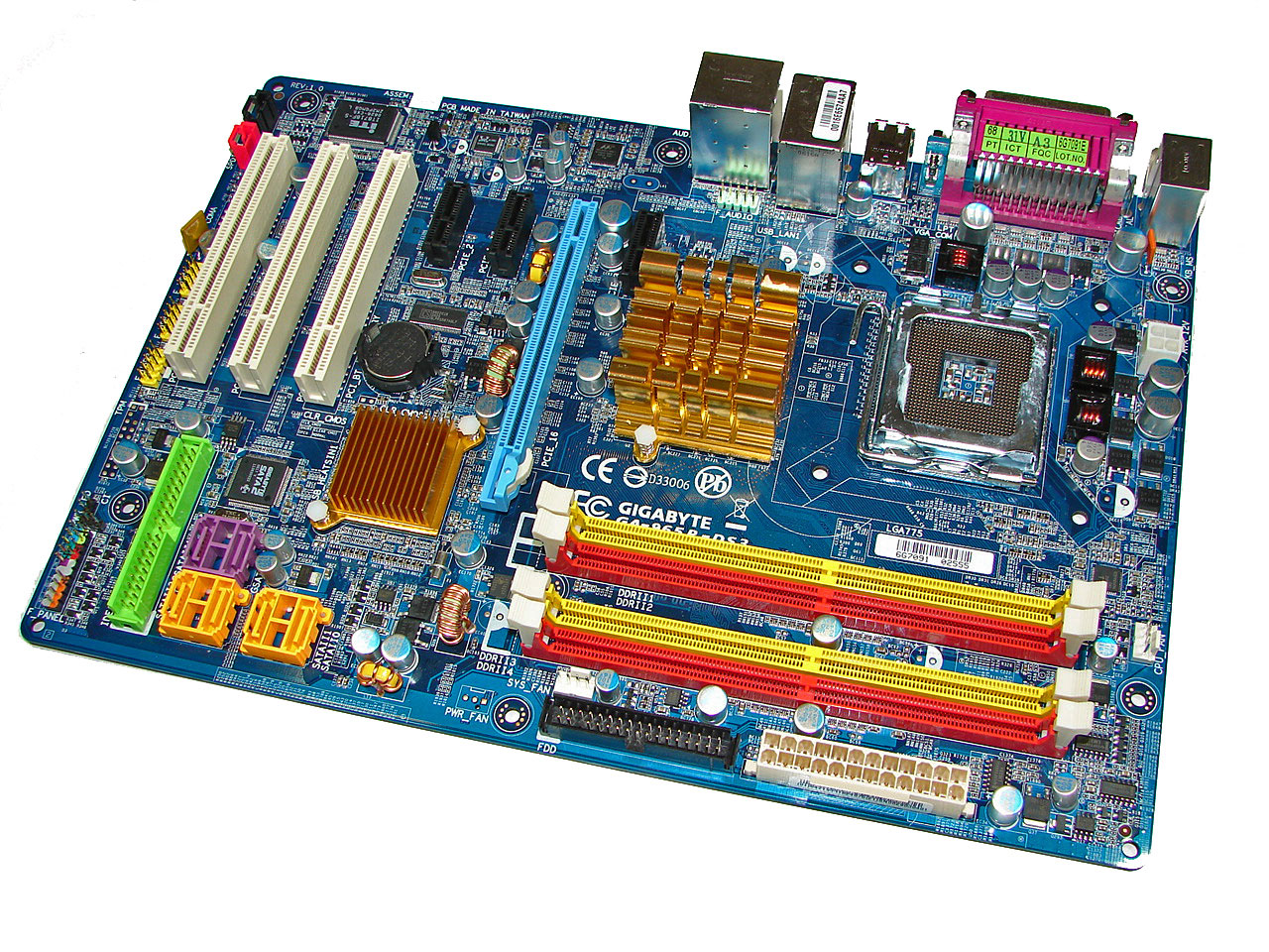
Gigabyte GA-965P-DS3: Board Layout and Features
Gigabyte has provided us with a well engineered board with a very good layout, though we would say the color combination does not have a central theme and lacks cohesiveness. We just feel if a manufacturer is going to take the time to add colors to a motherboard then at least do it with a graphics artist nearby. However, the board was a breeze to install in our case and all connections were easily reached. The board features a three-phase voltage regulator system that provided excellent stability throughout our testing. Gigabyte has recently switched their upper end boards to 100% use of Conductive Polymer Aluminum Solid Capacitors instead of the typical Electrolytic Capacitor. The purpose for this is to improve system durability and to provide for added stability under heavy load operations such as overclocking. With the latest BIOS release this board is also ready for the new Intel Core 2 Extreme Quad-Core (Kentsfield) processors.
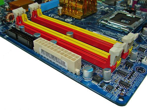
The DIMM module slots' color coordination is once again correct for dual channel setup based upon the premise of installing DIMMs in the same colored slots for dual-channel operation. The memory modules are slightly difficult to install with a full size video card placed in the PCI Express x16 slot. The 24-pin ATX power connector and black floppy drive connector are located along the edge of the board and behind the DIMM slots. The board only comes with two fan headers with the CPU fan header being located to the right of the first DIMM slot.
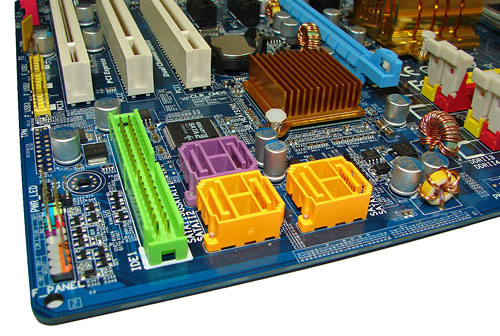
The four Intel ICH8 SATA ports are color coded yellow and the two JMicron JMB363 SATA ports are in a wonderful shade of lavender next to the green IDE connector. We found the positioning of the SATA ports to be excellent when utilizing the PCI 2.3 slots although we still prefer the IDE connector on the edge of the board to facilitate better cable management. The ICH8 is passively cooled with a gold colored low-rise heatsink and remained fairly cool to the touch throughout testing.
The chassis panel is located at the bottom left corner of the board. The clear CMOS jumper is located in between the battery and ICH8 chipset. This is a two pin configuration and requires the use of a pen to reach and is blocked if a card is installed in the first PCI slot. It seems to be a trend lately of the various manufacturers to place this jumper in the most inconvenient locations. Until the BIOS recovery programs work 100% of the time it would be nice to have this jumper out in the open, or even better go with the "button" design that we've seen used by a few manufacturers.
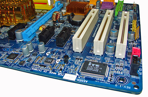
The board comes with (1) physical PCI Express x16 connector, (3) PCI Express x1 connectors, and (3) PCI 2.3 connectors. The layout of this design offers a very good balance of expansion slots for a mainstream performance board while providing excellent clearance space for graphics card utilization. The second PCI Express x1 slot will be blocked by a dual slot graphics card but considering the dearth of PCI Express peripherals this is fully acceptable. The first PCI Express x1 slot is a tight fit as a card installed in this slot will have minimal clearance between the MCH heatsink and video card.
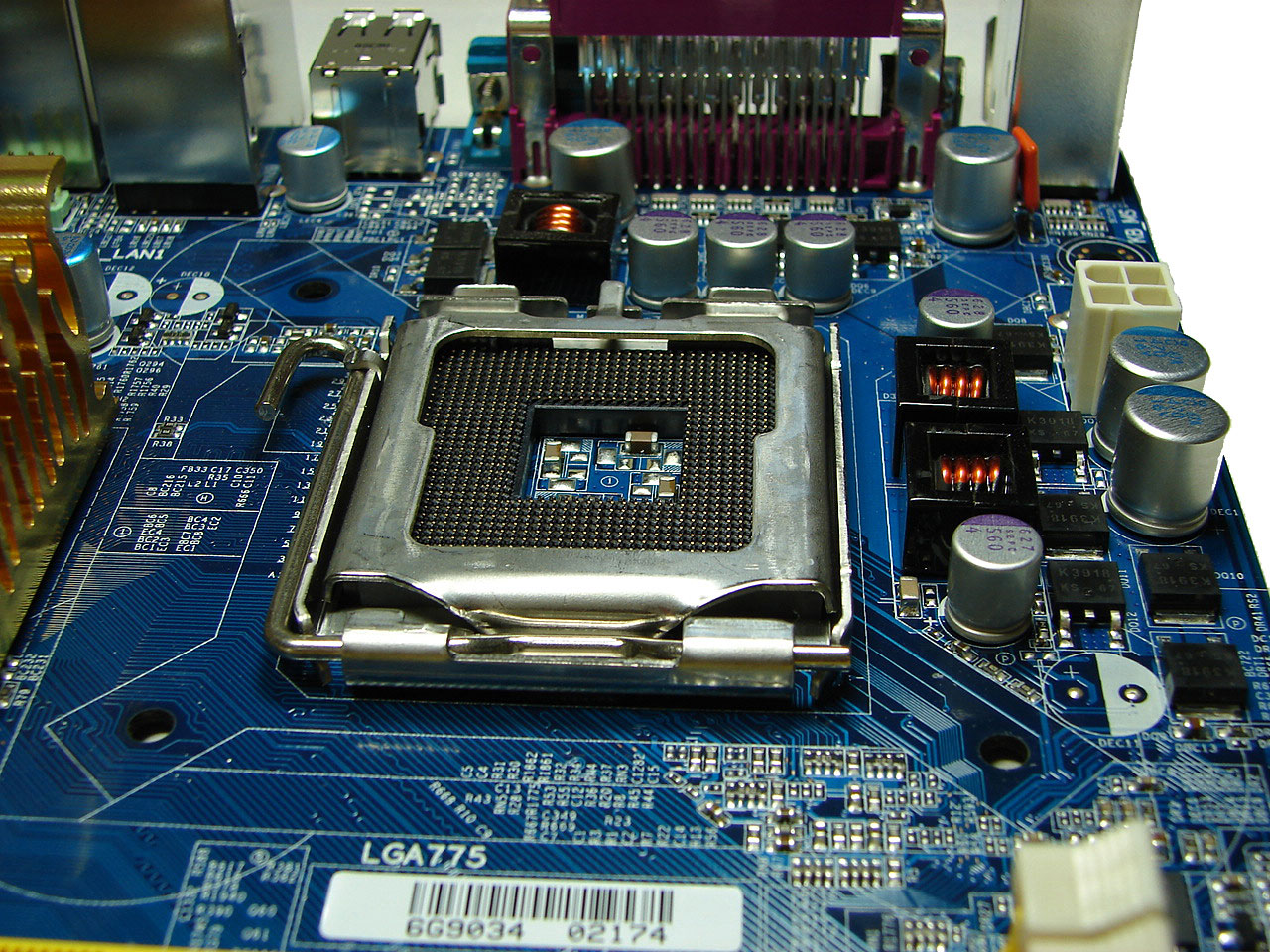
Upon entering the CPU socket area, we find an ample amount of room for the majority of cooling solutions. We utilized the stock heatsink/fan in our base testing but also verified several of the larger Socket-775 cooling solutions would fit in this area during our overclocking tests. The 4-pin ATX power connector is placed on the far right side of the board and did not interfere with our various cooling units.
The Intel P965 MCH chipset is passively cooled with a mid-rise heatsink unit that did not interfere with any installed peripherals. Unfortunately, this heatsink is not very good at keeping the MCH cool during heavy overclocking. Gigabyte has used this design for the past year but has generally shipped a small fan that attaches to it for additional cooling. This heatsink needs it when running the system above 400FSB. However, even if it were included this board only has two fan headers which is not representative of a performance oriented board.
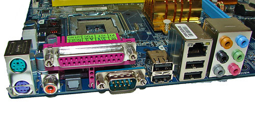
The rear panel contains the standard PS/2 mouse and keyboard ports along with serial and parallel ports for those who still require legacy peripherals. The panel also includes a LAN port, 4 USB ports, and two S/PDIF (optical out/coaxial out) ports. The LAN (RJ-45) port has two LED indicators representing Activity and Speed of the connection through the Marvell 88E8053 Gigabit PCI-E chipset. The audio panel consists of 6 ports that can be configured for 2, 4, 6, and 8-channel audio connections for the Realtek ALC 883 HD codec. The only item missing from our wish list would be a Firewire port if the board supported it.
 |
| Click to enlarge |
Gigabyte has provided us with a well engineered board with a very good layout, though we would say the color combination does not have a central theme and lacks cohesiveness. We just feel if a manufacturer is going to take the time to add colors to a motherboard then at least do it with a graphics artist nearby. However, the board was a breeze to install in our case and all connections were easily reached. The board features a three-phase voltage regulator system that provided excellent stability throughout our testing. Gigabyte has recently switched their upper end boards to 100% use of Conductive Polymer Aluminum Solid Capacitors instead of the typical Electrolytic Capacitor. The purpose for this is to improve system durability and to provide for added stability under heavy load operations such as overclocking. With the latest BIOS release this board is also ready for the new Intel Core 2 Extreme Quad-Core (Kentsfield) processors.
The DIMM module slots' color coordination is once again correct for dual channel setup based upon the premise of installing DIMMs in the same colored slots for dual-channel operation. The memory modules are slightly difficult to install with a full size video card placed in the PCI Express x16 slot. The 24-pin ATX power connector and black floppy drive connector are located along the edge of the board and behind the DIMM slots. The board only comes with two fan headers with the CPU fan header being located to the right of the first DIMM slot.
The four Intel ICH8 SATA ports are color coded yellow and the two JMicron JMB363 SATA ports are in a wonderful shade of lavender next to the green IDE connector. We found the positioning of the SATA ports to be excellent when utilizing the PCI 2.3 slots although we still prefer the IDE connector on the edge of the board to facilitate better cable management. The ICH8 is passively cooled with a gold colored low-rise heatsink and remained fairly cool to the touch throughout testing.
The chassis panel is located at the bottom left corner of the board. The clear CMOS jumper is located in between the battery and ICH8 chipset. This is a two pin configuration and requires the use of a pen to reach and is blocked if a card is installed in the first PCI slot. It seems to be a trend lately of the various manufacturers to place this jumper in the most inconvenient locations. Until the BIOS recovery programs work 100% of the time it would be nice to have this jumper out in the open, or even better go with the "button" design that we've seen used by a few manufacturers.
The board comes with (1) physical PCI Express x16 connector, (3) PCI Express x1 connectors, and (3) PCI 2.3 connectors. The layout of this design offers a very good balance of expansion slots for a mainstream performance board while providing excellent clearance space for graphics card utilization. The second PCI Express x1 slot will be blocked by a dual slot graphics card but considering the dearth of PCI Express peripherals this is fully acceptable. The first PCI Express x1 slot is a tight fit as a card installed in this slot will have minimal clearance between the MCH heatsink and video card.
 |
| Click to enlarge |
Upon entering the CPU socket area, we find an ample amount of room for the majority of cooling solutions. We utilized the stock heatsink/fan in our base testing but also verified several of the larger Socket-775 cooling solutions would fit in this area during our overclocking tests. The 4-pin ATX power connector is placed on the far right side of the board and did not interfere with our various cooling units.
The Intel P965 MCH chipset is passively cooled with a mid-rise heatsink unit that did not interfere with any installed peripherals. Unfortunately, this heatsink is not very good at keeping the MCH cool during heavy overclocking. Gigabyte has used this design for the past year but has generally shipped a small fan that attaches to it for additional cooling. This heatsink needs it when running the system above 400FSB. However, even if it were included this board only has two fan headers which is not representative of a performance oriented board.
The rear panel contains the standard PS/2 mouse and keyboard ports along with serial and parallel ports for those who still require legacy peripherals. The panel also includes a LAN port, 4 USB ports, and two S/PDIF (optical out/coaxial out) ports. The LAN (RJ-45) port has two LED indicators representing Activity and Speed of the connection through the Marvell 88E8053 Gigabit PCI-E chipset. The audio panel consists of 6 ports that can be configured for 2, 4, 6, and 8-channel audio connections for the Realtek ALC 883 HD codec. The only item missing from our wish list would be a Firewire port if the board supported it.


62 Comments
View All Comments
smn198 - Monday, October 23, 2006 - link
Would you be able to re-run using 4 drives for all of the tests please?
jonp - Sunday, October 22, 2006 - link
-- “…budget sector and includes boards from ECS, Foxconn, Intel, and Gigabyte.” – will the MSI P965 Neo-F be in this set?-- the Abit AB9 Pro feature set does not show the eSata port on the SI 3132 (two SATA). it does show a serial port on the i/o panel but not one in the picture.
-- The Biostar feature set shows 4 USB on the i/o panel when there are six in the picture.
JarredWalton - Sunday, October 22, 2006 - link
Fixed - thanks.powchi - Saturday, October 21, 2006 - link
Can I use a 20-pin power supply on these boards since all are using 24-pin connectors? Or will I be needing 20pin to 24pin adaptor?The PSU is an Enermax NoiseTaker EG475P-VE SFMA 470W ATX 12V v1.3.
Aikouka - Sunday, October 22, 2006 - link
Some motherboard manufacturers will no longer support your motherboard if they find out you've been running it with a 20-pin ATX plug or a 20->24-pin adapter. Just be safe and get a newer PSU :). I know DFI will no longer support the motherboard if it specifically asks for a 24-pin.JarredWalton - Saturday, October 21, 2006 - link
Technically, yes you can use 20-pin PSUs. Will they work, and will the system be stable? That varies. I haven't had any issues on the systems where I've done it, but if you do high overclocking it will likely become a serious issue.powchi - Saturday, October 21, 2006 - link
Jarred,So there's no need to use a 20pin to 24pin adaptor? What are the differences when using and not using an adaptor? Thanks.
lopri - Sunday, October 22, 2006 - link
No. As a matter of fact, the adapter should be avoided. Just plug the 20-pin connector to 24-pin receptacle with 4-pin left empty. Like Jarred said, it should work in theory and it does in practice. However, the quality of PSU and how intense is one's OC can affect the (long-term) stability.JarredWalton - Sunday, October 22, 2006 - link
I suppose the adapter *could* help, as it ensures power is available on all the 24-pins, but you're still taking the power from the same source so depending on how that works out it can actually make things worse. I would typically say that if you have a 400W or better PSU you should be fine with little to moderate OC'ing even with 20-pins. (I have an OCZ ModStream 450W that certainly works fine in a 939 board with a decent 2.0 to 2.6 GHz overclock.)lopri - Sunday, October 22, 2006 - link
Yes! Not to brag about myself or anything, but I went through countless Socket 939 Opterons on DFI NF4 SLI-D with original Antec TruePower EPS12V (20-pins, not the TP2 with 24-pins) including an Opteron 165 @3.0GHz (9x333). TCCD up to 325MHz/2.5-4-3-8! The setup was absolutely stable.