Intel P965: Mid-Range Performance Sector Roundup
by Gary Key on October 20, 2006 9:00 PM EST- Posted in
- Motherboards
Biostar TForce P965 Deluxe: Board Layout and Features
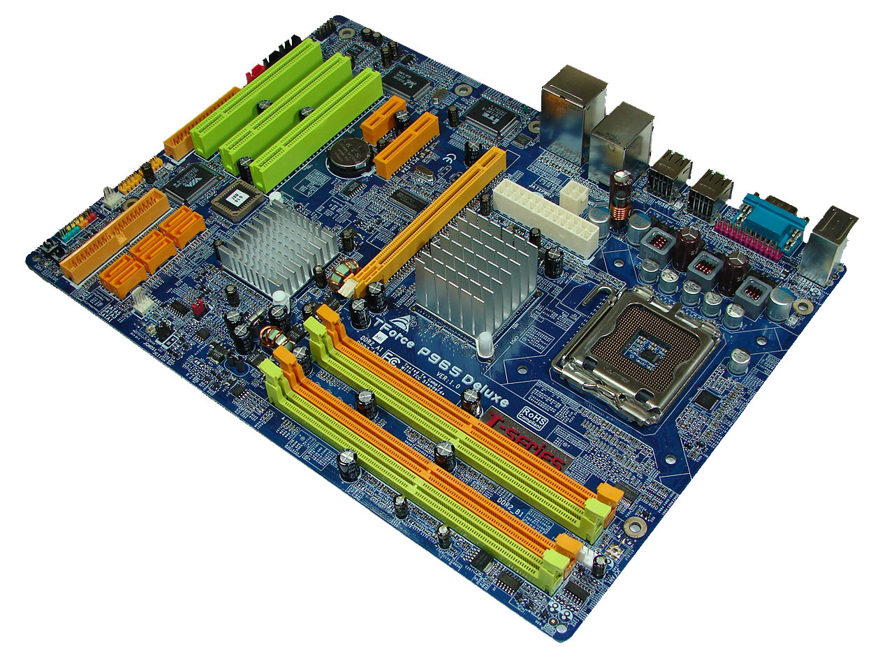
Biostar designed a well laid out board with an interesting color combination that grabs your attention without being overly aggressive. The board was extremely easy to install in our Cooler Master CM Stacker 830 case with all connections easily reached. However, the location of the 24-pin and 4-pin ATX connectors near the CPU area could cause cable management issues with larger air coolers like the Scythe Infinity. We also recommend installing the 4-pin ATX connector first as it is difficult to attach it with the 24-pin cable already installed. Biostar includes three fan headers although we wish there was an additional fan header near the I/O panel. The board features a three-phase voltage regulator system that provided excellent stability throughout our testing.
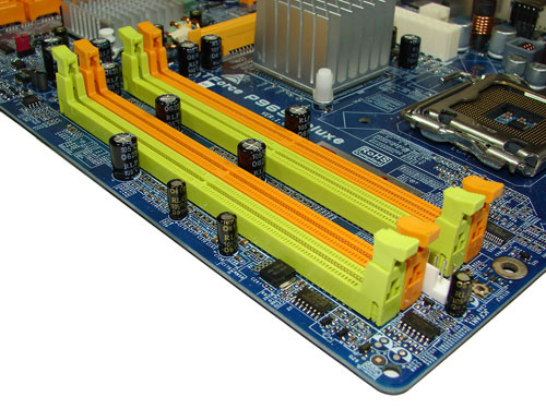
The DIMM module slots' color coordination is correct for dual channel setup based upon the premise of installing DIMMs in the same colored slots for dual-channel operation. It is nearly impossible to install memory modules with a full size video card placed in the PCI Express x16 slot. Biostar places the CPU fan header in between the number two and three memory module and it is a fair distance to reach for most CPU fan/heatsink cables. The board features a total of three fan headers. A fourth one would have been preferred near the I/O panel.
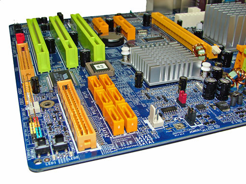
The six Intel ICH8R SATA ports are orange and are conveniently located to the left of the ICH8R Southbridge and second fan header. The SATA ports feature the newer clamp and latch design. We found the positioning of the SATA ports to be very good when utilizing the PCI 2.3 slots. The ICH8R is passively cooled and remained cool to the touch throughout testing.
The clear CMOS jumper is color coded black and is located in an easy access location at the edge of the board near the second fan header. Biostar includes a power on and reset button at the bottom corner of the board next to the VIA IDE connector. The chassis panel, third fan header, and USB connectors are located along the left edge of the board.
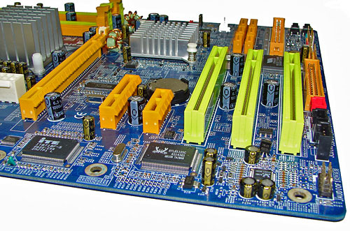
The board comes with (1) physical PCI Express x16 connector, (1) PCI Express x4, (1) PCI Express x1, and (3) PCI 2.3 connectors. The layout of this design offers one of the best single x16 connector designs we have worked with as none of the slots are blocked when using a dual slot video card in the x16 slot. We have to give credit to Biostar for this impressive layout and combination of slots on a mid-range board. However, the sacrifice for this layout is the inability to change memory modules with most video cards installed. The floppy drive connector is located at the edge of the board next to the last PCI slot. We would just as well have this connector disappear at this time.
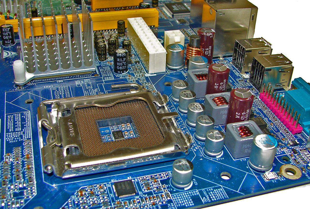
Getting back to CPU socket area, we find a fair amount of room for alternative cooling solutions. We utilized the stock heatsink/fan in our normal testing but also verified a few larger Socket-775 air cooling solutions would fit in this area during our overclocking tests. The Intel P965 MCH chipset is passively cooled with a mid-rise heatsink unit that did not interfere with any installed peripherals. However, it was very difficult routing the ATX power cables to their connectors with a cooling solution like the Tuniq Tower 120 installed. Fortunately our power supply had cables that were sleeved that allowed us to bend the cables around the heatsink area without worry about ripping a wire open.
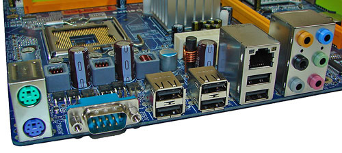
The rear panel contains the PS/2 mouse and keyboard ports, LAN port, and 6 USB 2.0 ports. The LAN (RJ-45) port has two LED indicators representing Activity and Speed of the connection through the Realtek RTL8110SC Gigabit PCI-E chipset. The audio panel consists of 6 ports that can be configured for 2, 4, 6, and 8-channel audio connections for the Realtek ALC 883 HD codec. The panel also has a serial port and we would have preferred a S/PDIF optical out port to have been included in this area.
 |
| Click to enlarge |
Biostar designed a well laid out board with an interesting color combination that grabs your attention without being overly aggressive. The board was extremely easy to install in our Cooler Master CM Stacker 830 case with all connections easily reached. However, the location of the 24-pin and 4-pin ATX connectors near the CPU area could cause cable management issues with larger air coolers like the Scythe Infinity. We also recommend installing the 4-pin ATX connector first as it is difficult to attach it with the 24-pin cable already installed. Biostar includes three fan headers although we wish there was an additional fan header near the I/O panel. The board features a three-phase voltage regulator system that provided excellent stability throughout our testing.
The DIMM module slots' color coordination is correct for dual channel setup based upon the premise of installing DIMMs in the same colored slots for dual-channel operation. It is nearly impossible to install memory modules with a full size video card placed in the PCI Express x16 slot. Biostar places the CPU fan header in between the number two and three memory module and it is a fair distance to reach for most CPU fan/heatsink cables. The board features a total of three fan headers. A fourth one would have been preferred near the I/O panel.
The six Intel ICH8R SATA ports are orange and are conveniently located to the left of the ICH8R Southbridge and second fan header. The SATA ports feature the newer clamp and latch design. We found the positioning of the SATA ports to be very good when utilizing the PCI 2.3 slots. The ICH8R is passively cooled and remained cool to the touch throughout testing.
The clear CMOS jumper is color coded black and is located in an easy access location at the edge of the board near the second fan header. Biostar includes a power on and reset button at the bottom corner of the board next to the VIA IDE connector. The chassis panel, third fan header, and USB connectors are located along the left edge of the board.
The board comes with (1) physical PCI Express x16 connector, (1) PCI Express x4, (1) PCI Express x1, and (3) PCI 2.3 connectors. The layout of this design offers one of the best single x16 connector designs we have worked with as none of the slots are blocked when using a dual slot video card in the x16 slot. We have to give credit to Biostar for this impressive layout and combination of slots on a mid-range board. However, the sacrifice for this layout is the inability to change memory modules with most video cards installed. The floppy drive connector is located at the edge of the board next to the last PCI slot. We would just as well have this connector disappear at this time.
 |
| Click to enlarge |
Getting back to CPU socket area, we find a fair amount of room for alternative cooling solutions. We utilized the stock heatsink/fan in our normal testing but also verified a few larger Socket-775 air cooling solutions would fit in this area during our overclocking tests. The Intel P965 MCH chipset is passively cooled with a mid-rise heatsink unit that did not interfere with any installed peripherals. However, it was very difficult routing the ATX power cables to their connectors with a cooling solution like the Tuniq Tower 120 installed. Fortunately our power supply had cables that were sleeved that allowed us to bend the cables around the heatsink area without worry about ripping a wire open.
The rear panel contains the PS/2 mouse and keyboard ports, LAN port, and 6 USB 2.0 ports. The LAN (RJ-45) port has two LED indicators representing Activity and Speed of the connection through the Realtek RTL8110SC Gigabit PCI-E chipset. The audio panel consists of 6 ports that can be configured for 2, 4, 6, and 8-channel audio connections for the Realtek ALC 883 HD codec. The panel also has a serial port and we would have preferred a S/PDIF optical out port to have been included in this area.


62 Comments
View All Comments
JarredWalton - Friday, October 20, 2006 - link
I think that was a temporary glitch where the article went live before the last page's text was updated. Shame on you for skipping straight to the end.... ;)BadThad - Sunday, October 22, 2006 - link
Is the v1.02G Asus P5B-E using all solid capacitors? I read a press release stating that Asus was releasing the "P4B-E Plus" version with all solid caps. Rumor says the "Plus" version will not be sold in the USA.....arrgggggg. Tell me that's not true. I want the solid caps for long-term reliability. I'm wondering if our "Plus" is actually the v1.02G?