Gigabyte GA-G1 975X: Features
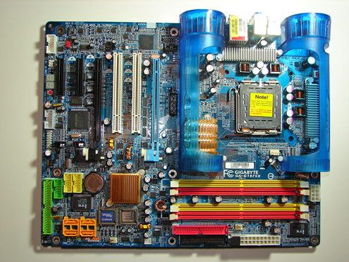
Gigabyte designed a generally well laid out board with all major connections easily reached. The board is lacking most clearance issues and was very easy to install in a mid-size ATX case. Gigabyte did an excellent job with the color coordination of the various peripheral slots and connectors.
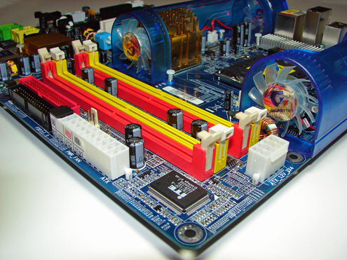
The DIMM module slots' color coordination is correct for dual channel setup. The memory modules can easily be changed with a full size video card installed in the first PCI Express x16 slot. The power plug placement favors standard ATX case design and the power cable management is excellent. The floppy drive port connector and primary IDE port connector are conveniently located on the edge of the board along with the 24-pin ATX power connector. The 8-pin EATX power connector is located next to the memory slots and after installation in the case we actually favored this location over the traditional area near the processor.
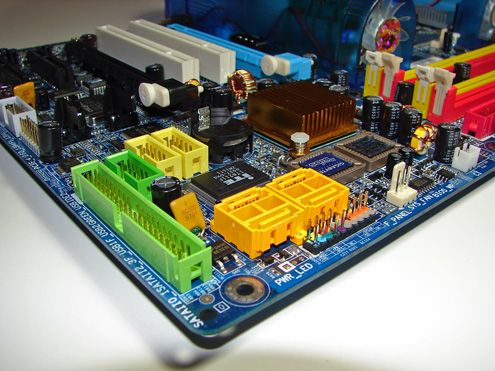
The ITE 8211F IDE port connector and Intel SATA II ports are conveniently located in the bottom section of the board. The SATA II ports feature the new clamp and latch design. Gigabyte's standard Dual-Bios setup and additional Intel USB connectors are also located in this area.
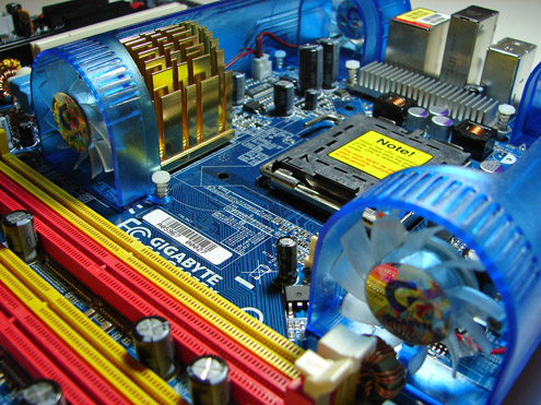
The Northbridge (MCH) is passively cooled with a large heatsink designed to fit into the confine of the Turbojet cooling system. The heatsink was cool to the touch during our initial testing.
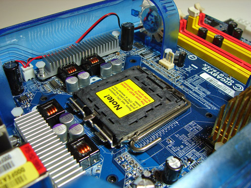
The CPU socket area has an ample amount of room for alternative cooling solutions. We utilized the stock Intel heat sink but also verified several aftermarket cooling systems would fit in this area during our tests. However, due to the Turbojet fan housings, installation of certain heatsinks could be problematic.

The rear panel contains the standard PS/2 mouse and keyboard ports, LAN (RJ-45) port, and 2 USB ports. The audio panel consists of 3 ports that can be configured for a variety of audio connections.
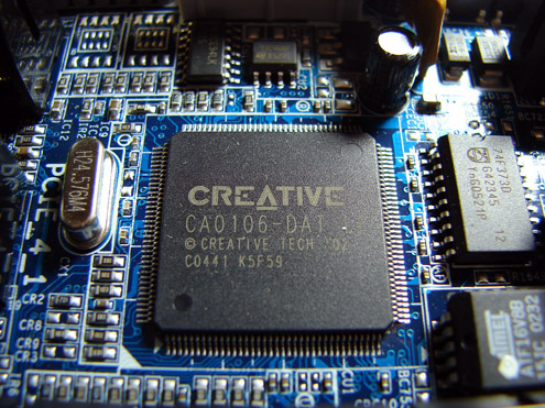
The board is equipped with the Creative Sound Blaster Live! 24-bit (CA0106-Dat Codec) audio solution. We will be testing this audio solution against several on-board and add-in audio offerings in the full review.


30 Comments
View All Comments
johnsonx - Friday, November 11, 2005 - link
Gary,From an airflow perspective, wouldn't it make more sense to have all the fans blowing the same direction? From the pictures and your description, it appears the while the fans at the backplate are blowing out, as they should, the 2nd set of fans attempt to blow air back at the memory.
The trouble is that those 2nd fans are trying to pull air against the general airflow direction in the case, and whatever air they do blow over the RAM will be warm from the CPU and other heatsinks in those platic tunnels.
I think in a real-life case, the 2nd set of fans should blow towards the back of the case, drawing cool air from the front of the case past the DIMMs, thus creating a wind-tunnel effect to more effectively draw the hot exhaust from the CPU HSF to the back fans and out of the case.
Perhaps if it can be done, you could try swapping the 2nd fans around to get them blowing the other way and do some measurements. I can't tell if it's possible from the pictures; the tunnels and fan mount brackets look like they could be one-piece. I suppose that you could reverse the polarity of the power pins to spin them backwards, but those fans don't look like they'd move much air spinning the wrong way.
Yes, I do realize that Gigabyte's Engineers must have worked on this, but I've had 'engineers' tell me riduculous things about airflow in the past that I proved wrong by simply flipping the fans around. One that comes to mind from awhile back was a KryoTech Super-G that had the back fan blowing in and the front fan blowing out... their engineers INSISTED that it was supposed to be that way, that they had tested, blah, blah, blah... after feeling the side panel getting warm and nearly burning my hand on the SCSI drive in the bay, I reversed the fans and all was well. And that was a system with NO cpu heat at all!
Airflow in an ATX case should always be front to back, bottom to top.
Gary Key - Friday, November 11, 2005 - link
This was exactly my first thought when I looked at the board, read the engineering information, and then powered on the board. My first reaction was the thermals coming off the MCH would be blown right across the memory slots and then getting swept into the power supply or back over the CPU area creating additional heat. I think I was right to some degree. ;->
However, Gigabyte is recommending and has provided pictures of their preferred CPU cooling system which consists of a cooler that is designed like their G-Power series that blows air over the entire CPU surface area. According to Gigabyte their reduction in thermals at the memory, MCH, and MOFSETs were accomplished with this combination. I am trying their cooling suggestions currently along with swapping the 40mm fans with others to blow in opposite directions. This is why I was not about to publish their test results until we had a chance to fully review the system and take our own measurements.
I have not completed testing and still have additional cooling units to try along with additional measurements from the stock heatsink/fan. My initial thoughts and test results favor the Asus 8-phase setup with the fanless heat pipe system although the Gigabyte design actually works well. I will have measurements and a final synopsis in the full article. Until then if I find something of significance I will post an update.
bldckstark - Friday, November 11, 2005 - link
I am somewhat confused by the above listed statement as it can mean several things to me.
Is there a specification for dual channel slot color coding, or are you stating your personal preference?
I know it is nitpicky, but I am curious.
Thanks for the article, you did a great job, first time or not.
Gary Key - Friday, November 11, 2005 - link
There is not a hard standard for the color designation. Most manufacturers have started color-coding the various port connectors and slots but in some cases these colors do not mean anything. With the memory slots it is now customary to color code the slots to signify which slots need to be filled to enable the dual channel memory capabilities of the board. Instead of signifying in the user's manual to utilize slot one and three or two and four for dual channel capability the quick setup sheets can now use a visual color to represent the slot numbers. It is easier to understand this way and helps when you cannot locate the user manual while you are stuck under a desk with low light conditions. ;->
The main problem is that some boards (earlier review this year) have the first and second slots the same color and slots three and four a different color yet you have to use slot one and three for dual channel. This is confusing to others and me as it is not intuitive and does not follow a "soft" standard that has developed regarding the memory slot color-coding.
johnsonx - Friday, November 11, 2005 - link
Yeah, I've found the color coding of the memory slots pretty useless, as I can never be sure whether they mean to put the two dimms in the two slots that are colored the same, or colored different. I always just figure the first two slots are one channel, and the other pair are the other channel (usually there's a gap between the two pairs, but not always).Personally, for me it makes more logical sense to have the slots the same color within a channel, so you put the two dimms into different color slots. In other words, the different color should signify a different channel. This scheme also lends itself well to single-channel boards - their slots should all be one color, signifying one channel.
That said, I can also understand the logic of making the first slot of each channel the same color, and the second slot of each channel a different color. So then you put each pair of DIMMs in the same-color slots.
Either way though, they (the MB manufacturers as a group) really ought to pick one method and stick to it. For now, I'll just ignore the colors.
rqle - Friday, November 11, 2005 - link
Can i see a pic of the backplate I/O shield? Old request, probably not even gonna get read. But it just look interesting.Gary Key - Friday, November 11, 2005 - link
Hi,I will see what I can do for you.
Marlowe - Friday, November 11, 2005 - link
Is this the final implementation of the 975x chipset? I heard there were going to be some sort of an upgrade along its lifetime, as the "current" 975x based motherboards does not support the future processors conroe and yonah? (because those two will be pin compitable right?) More PCI-Express lanes as seen in ATI's new RD580 chipset would also be nice.Gary Key - Friday, November 11, 2005 - link
Good Day,I am awaiting word from Intel about the 975X progression path and will report any findings along with additional technical information in the full article. This article was meant as a preview and since the chipset has not officially launched there were details I could not provide at this time. I fully agree that additional PCI-Express lanes would be nice. If I receive additional information from Intel before the full article is released I will update this preview.
xsilver - Friday, November 11, 2005 - link
how is putting a turbo on a scooter going to help?? ;)and i guarantee that all 4 of those tiny fans are going to either:
1) die in 4 months
2) sound like a turbocharger in 4 months
I think the next step up should actually be intergration with the case, their is just too much contstriants otherwise (especially working with the oldish ATX structure)