The Corsair Carbide 400Q Case Review
by E. Fylladitakis on April 29, 2016 9:00 AM EST- Posted in
- Cases/Cooling/PSUs
- Corsair
- ATX
- E-ATX
- Carbide
Test setup
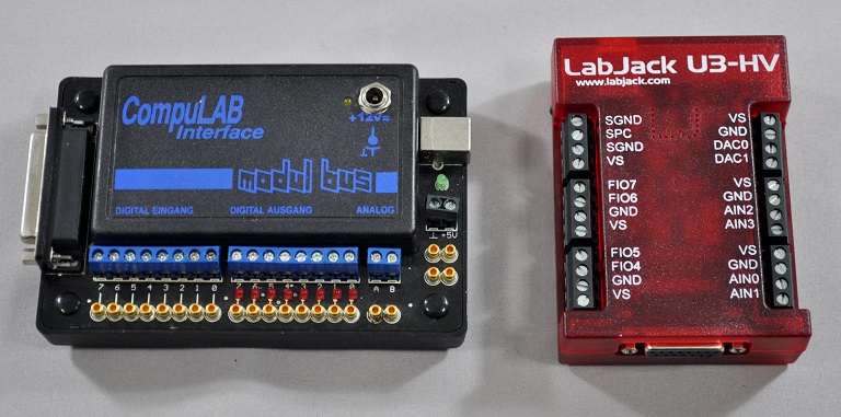
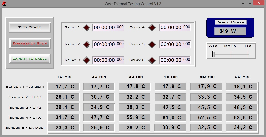
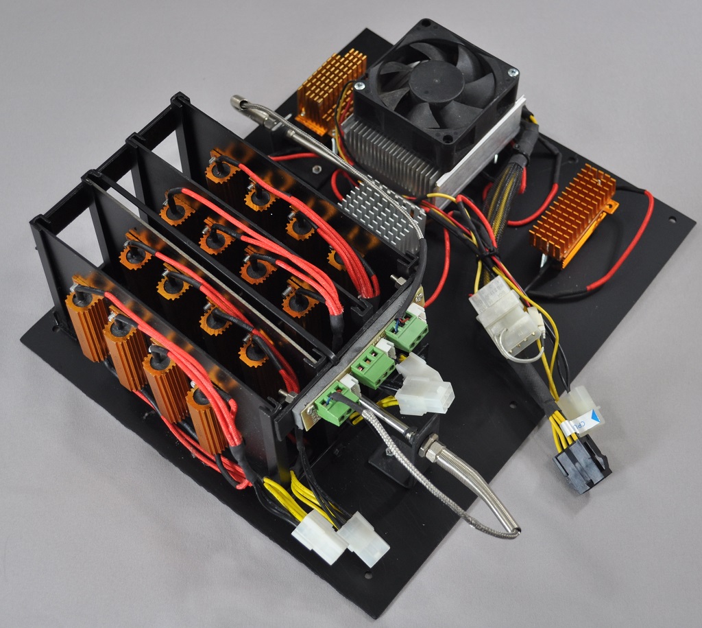
Professional testing requires the emulation of real-world situations but with repeatable results; thus, a perfectly controllable test setup and environment are required, especially for comparable results. Testing the thermal performance of any case with a typical real-world setup technically limits the comparability of the results to this setup alone, as an active system interacts with its environment and the change of a single component would alter myriads of variables. As such, we developed synthetic loads that emulate the thermal output of real systems, which however are passive, steady and quantifiable. As such, the thermal testing now displays the thermal capabilities of the case alone, as if it would have to deal with the entire thermal load by itself, regardless of the system that would be installed inside it. Laboratory data loggers are being used to monitor the PT100 sensors and control the safety relays, which are fully accessible via our custom software. Three such loads have been developed; the ATX version simulates a 200W CPU, 50W VRM, 30W RAM and 4 × 120W GPU card thermal load. Finally, three 3.5" HDD dummy loads have also been created, with each of them converting 30 W of electrical power to thermal, bringing the total thermal load of the ATX test setup up to 850 Watts. As such, the thermal load is immense and only the best of cases will be able to handle it for more than a few minutes, we are also performing a test with a thermal load of 400W, with all of the aforementioned components except the HDD drives at about 42% power, which is more suitable for the majority of cases.
Thermal testing has been performed with all of the case's stock fan operating at maximum speed. Noise testing has been performed with a background noise level of 30.4dB(A). Advanced noise testing is also being performed, in order to assess the ability of the case to dampen the noise of the components installed inside it. This includes the installation of two noise-generating sources (strong fans) inside the case, one positioned approximately over the first expansion slot and one over the CPU area, which generate ≈ 44.2 dB(A) when unobstructed. During the advanced noise test, all stock cooling options of the case are entirely disabled.
Note: The Carbide 400Q can only hold two 3.5" drives, so only two such loads are installed and the actual maximum thermal load is 820 Watts.
Results and discussion
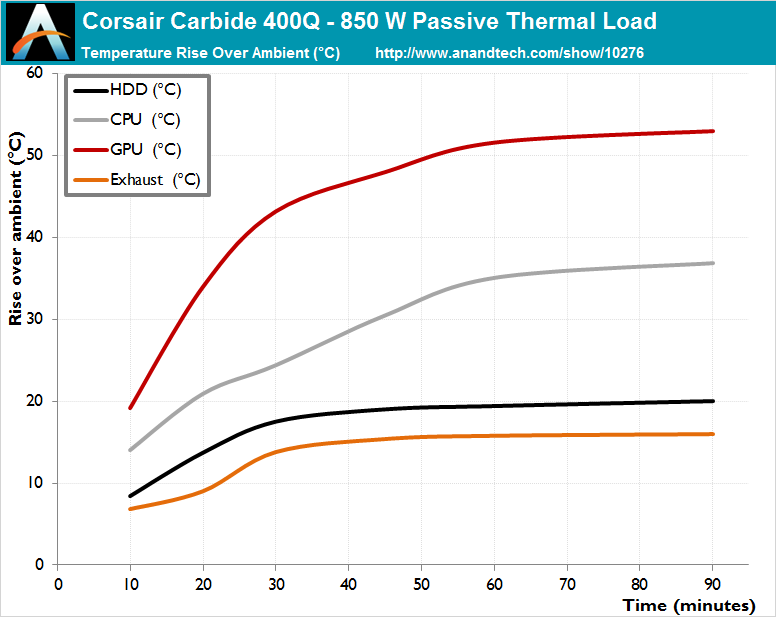
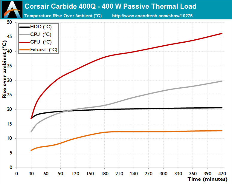
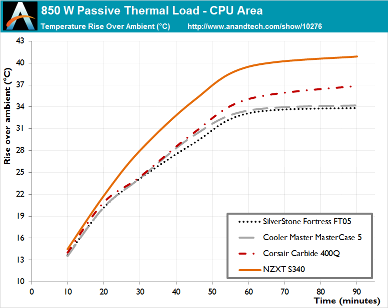
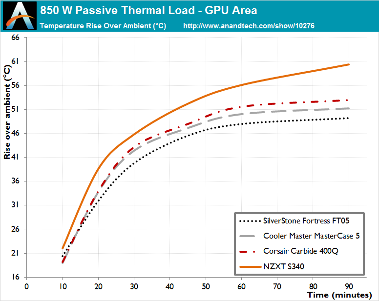
Considering the size and class of the Corsair Carbide 400Q, its performance landed almost exactly where we anticipated it would. Having insulated panels and inferior stock cooling than the SilverStone Fortress FT05, it falls a little behind, but its thermal performance is unexpectedly better than that of the similar (yet significantly smaller) NZXT S340. It cannot outperform but holds its ground well against larger tower cases, such as the Cooler Master MasterCase 5 and the Corsair 450D.
Corsair has installed two of their AF series fans inside the Carbide 400Q, which are designed to provide high airflow with low noise levels, making them the ideal choice as case fans. Combined with the sound dampening material, they made the Carbide 400Q one of the lowest noise ATX tower cases that we have ever tested. The Carbide 400Q showed very good sound dampening capabilities as well, reducing the sound pressure generated by our dummy noise source by 5 dB(A), from 44.2 dB(A) to 39.2 dB(A). The dB(A) scale is logarithmic and that translates to a sound pressure reduction of over 60%, which is easily discernible by the human ear.
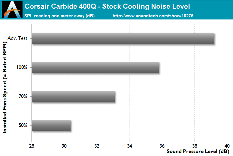
Nevertheless, do note that the above acoustic performance figures were for the stock cooling only and with the top panel installed. If the top panel is removed, even if no other fans are installed, all figures increase by nearly 2 dB(A), nearly negating all of the advantage the Carbide 400Q has over most typical ATX tower cases.


63 Comments
View All Comments
ononhk - Monday, May 9, 2016 - link
VERY POOR CASE !!!!! (400Q)<a href="http://www.imagebam.com/image/b50845482435809"... target="_blank"><img src="http://thumbnails116.imagebam.com/48244/b508454824... alt="imagebam.com"></a>
skew88 - Wednesday, May 11, 2016 - link
That's very worrying. When did this problem start? Do you have an idea what might have caused it?I would also like to chime in with a piece of criticism: The latches of the front panel are just extremely prone to breaking off. In fact, I saw a Corsair employee manage to do it at a Corsair booth the day after I did it myself! How did this make it through quality control!?
Earl-J - Saturday, August 6, 2016 - link
* * *Okay, for those of us non-techies who very rarely get inside their own computers, let alone pry and snap things inside to get a better view, the direction. . .
"To remove the two plastic covers that separate the PSU and HDD area from the rest of the case, the HDD cover has to come off first, then the PSU cover."
means absolutely nothing.
I can see the one piece (HDD) on the desk and the second piece (PSU)
still attached to the inside of the main box... I know which one comes out
first just by looking at the picture.
I see the snap-latches that need to be pushed in order to get the covers out.
The HDD latch has a cover of some sort on it that cannot be pushed, slid, or lifted...
I can feel the pins under the chassis... once I get them to a position where I can pull the front up from the bottom, do I yank it up... push something else... or slide it...?
LOL
I've considered myself a logical person for many, many years...
but this box has me stumped...
(sigh)
LOL