Features
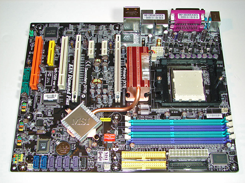
MSI designed a very well laid out board with all major connections easily reached except for the eight-pin ATX power connector when a larger air or water cooling system is utilized. The MSI layout provides excellent clearance for cards and components and was easy to install in a mid-size ATX case. Although the board features a 3-phase voltage regulator power design it provided excellent stability, power regulation, and allowed for an impressive level of overclocking. The board provides 2 chassis, 1 CPU, and 1 Northbridge fan header, but as mentioned the BIOS does not allow temperature based fan control of the chassis headers.
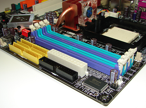
The DIMM module slots are not color coordinated correctly for dual channel setup. If the user utilizes the two green or two purple memory slots then the board will reward you with single channel operation unless all four slots are utilized. Also note that if you only use two DIMMs, a correct dual channel setup will place the DIMMs in adjacent slots; this will generally create slightly higher RAM temperatures, though in practice this will only be a problem for more extreme overclocks. The memory modules are fairly easy to install with a full size video card placed in the first PCI Express x16 slot.
The black floppy drive and yellow IDE primary connectors are conveniently placed along the edge of the board. The white 24-pin ATX power connector and yellow secondary IDE connector are located in between the last memory module slot and the floppy and secondary IDE connectors respectively. This layout should work very well for most users.
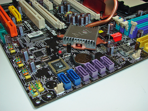
The nForce4 SATA port connectors are color coded purple while being located along the board's edge and beneath the battery. The SATA port connectors did not present any connection issues when utilizing the board in SLI operation. The second system fan header is located to the right of the SATA ports and below the MSI Core Cell chipset and red labeled memory voltage switch block. The nForce4 SLI chipset (i.e. Southbridge) is passively cooled with a low rise heatsink and located in a position that does not interfere with the secondary PCI Express x16 or primary 32-bit PCI slot when occupied. The heatsink is attached to the Northbridge fan/heatsink via a heatpipe design.
The blue Silicon Image SATA ports are located below the BIOS chip and to the left of the nForce4 SATA connectors. The first system fan header is located to the left of the Silicon Image SATA ports followed by the chassis panel connectors. The yellow USB 3/4/5 headers are located along the edge of the board. The CMOS reset block is the red button to the left of the Southbridge. If you ever have occasion to clear the CMOS settings, you'll find the button to be far more convenient than the traditional jumper designs.
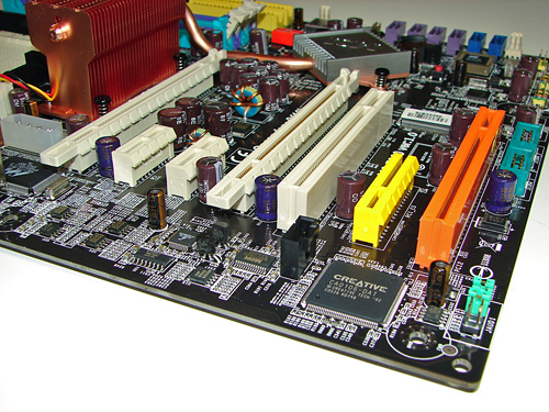
The board comes with (2) physical PCI Express x16 connectors, (2) PCI Express x1 connectors, (1) PCI Express x4 connector, and (2) 32-bit PCI 2.3 connectors. The layout of this design offers a good balance of expansion slots for a mainstream board. The first physical PCI Express x16 connector is color coded white and located uncomfortably close to the C51D Northbridge fan/heatsink unit. The two PCI Express x1 connectors are located next followed by the second white PCI Express x16 connector. The first 32-bit PCI connector is located next and followed by the yellow PCI Express x4 connector and second 32-bit PCI connector that is color coded orange.
We did not have any issues installing our NVIDIA 7900GTX video cards in the first and second x16 PCI Express slots. These dual slot configuration cards will physically render the first PCI Express x1 and 32-bit PCI slots useless. We did not have any issues utilizing these slots with video cards containing single slot cooling systems. Looking back at the slot configuration, we wish MSI would have dropped one of the PCI Express x1 slots for another 32-bit PCI slot, as the number of PCI expansion cards and their usefulness continues to surpass that of PCI-E x1 cards. This is a minor point really, but anyone looking to install two dual slot GPUs with a sound card and a TV tuner will need to opt for a PCI-E tuner card. Unfortunately, there are no PCI-E audio or HDTV solutions at present.
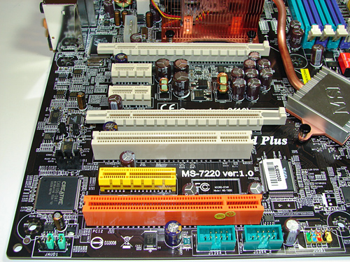
The Front Panel Audio connector and two green IEEE 1394A connectors are located along the edge of the board. If you use both internal Firewire headers, that means you have a total of three Firewire ports - probably more than most people will need, but certainly nothing to complain about. The black CD Audio In connector is located to the left of the first 32-bit PCI connector.
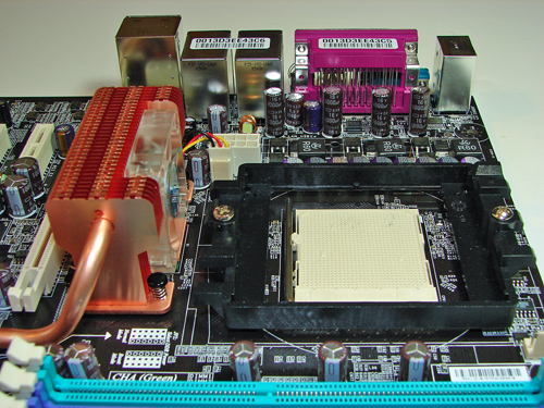
Returning to the CPU socket area, we find a limited amount of room for alternative cooling solutions. We utilized the stock AMD heat sink but also verified several aftermarket cooling systems such as the Thermaltake Big Typhoon and Zalman CNPS9500 would fit in this area during our tests. Due to the high rise fan/heatsink covering the NVIDIA C51D Northbridge chipset, the installation of larger air or water-cooling solutions will be an issue. We were able to install our Tuniq Tower 120 but it rubbed against the Northbridge fan/heatsink.
MSI places the eight-pin ATX12V auxiliary power connector at the top left of the CPU socket area - it works fine with the older four-pin ATX12v connectors as well, although this is not mentioned in the manual. This connector is located in an unusual position and could hamper airflow with cabling that crosses directly over the CPU heatsink/fan. We did not have any issues in our particular setup, but the choice of case and HSF should be made carefully. There is also a four-pin molex connector located to the left of the ATX12V connector that must be utilized for dual card operation - one more cable to potentially route around the CPU area.
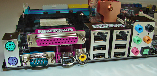
The rear panel contains the standard PS/2 mouse and keyboard, serial, parallel, and 4 USB ports. Located to the right of the serial port and below the parallel port is the IEEE 1394 port and S/PDIF Coaxial out port. Located next are the four USB 2.0 ports with the RJ-45 LAN ports on top. The audio panel is located to the right of these ports and consists of 5 ports that can be configured for 2, 4, 5.1, and 7.1 channel audio connections. The S/PDIF Optical (TOS Link) out port is located to the right of the pink MIC port.
MSI designed a very well laid out board with all major connections easily reached except for the eight-pin ATX power connector when a larger air or water cooling system is utilized. The MSI layout provides excellent clearance for cards and components and was easy to install in a mid-size ATX case. Although the board features a 3-phase voltage regulator power design it provided excellent stability, power regulation, and allowed for an impressive level of overclocking. The board provides 2 chassis, 1 CPU, and 1 Northbridge fan header, but as mentioned the BIOS does not allow temperature based fan control of the chassis headers.
The DIMM module slots are not color coordinated correctly for dual channel setup. If the user utilizes the two green or two purple memory slots then the board will reward you with single channel operation unless all four slots are utilized. Also note that if you only use two DIMMs, a correct dual channel setup will place the DIMMs in adjacent slots; this will generally create slightly higher RAM temperatures, though in practice this will only be a problem for more extreme overclocks. The memory modules are fairly easy to install with a full size video card placed in the first PCI Express x16 slot.
The black floppy drive and yellow IDE primary connectors are conveniently placed along the edge of the board. The white 24-pin ATX power connector and yellow secondary IDE connector are located in between the last memory module slot and the floppy and secondary IDE connectors respectively. This layout should work very well for most users.
The nForce4 SATA port connectors are color coded purple while being located along the board's edge and beneath the battery. The SATA port connectors did not present any connection issues when utilizing the board in SLI operation. The second system fan header is located to the right of the SATA ports and below the MSI Core Cell chipset and red labeled memory voltage switch block. The nForce4 SLI chipset (i.e. Southbridge) is passively cooled with a low rise heatsink and located in a position that does not interfere with the secondary PCI Express x16 or primary 32-bit PCI slot when occupied. The heatsink is attached to the Northbridge fan/heatsink via a heatpipe design.
The blue Silicon Image SATA ports are located below the BIOS chip and to the left of the nForce4 SATA connectors. The first system fan header is located to the left of the Silicon Image SATA ports followed by the chassis panel connectors. The yellow USB 3/4/5 headers are located along the edge of the board. The CMOS reset block is the red button to the left of the Southbridge. If you ever have occasion to clear the CMOS settings, you'll find the button to be far more convenient than the traditional jumper designs.
The board comes with (2) physical PCI Express x16 connectors, (2) PCI Express x1 connectors, (1) PCI Express x4 connector, and (2) 32-bit PCI 2.3 connectors. The layout of this design offers a good balance of expansion slots for a mainstream board. The first physical PCI Express x16 connector is color coded white and located uncomfortably close to the C51D Northbridge fan/heatsink unit. The two PCI Express x1 connectors are located next followed by the second white PCI Express x16 connector. The first 32-bit PCI connector is located next and followed by the yellow PCI Express x4 connector and second 32-bit PCI connector that is color coded orange.
We did not have any issues installing our NVIDIA 7900GTX video cards in the first and second x16 PCI Express slots. These dual slot configuration cards will physically render the first PCI Express x1 and 32-bit PCI slots useless. We did not have any issues utilizing these slots with video cards containing single slot cooling systems. Looking back at the slot configuration, we wish MSI would have dropped one of the PCI Express x1 slots for another 32-bit PCI slot, as the number of PCI expansion cards and their usefulness continues to surpass that of PCI-E x1 cards. This is a minor point really, but anyone looking to install two dual slot GPUs with a sound card and a TV tuner will need to opt for a PCI-E tuner card. Unfortunately, there are no PCI-E audio or HDTV solutions at present.
The Front Panel Audio connector and two green IEEE 1394A connectors are located along the edge of the board. If you use both internal Firewire headers, that means you have a total of three Firewire ports - probably more than most people will need, but certainly nothing to complain about. The black CD Audio In connector is located to the left of the first 32-bit PCI connector.
Returning to the CPU socket area, we find a limited amount of room for alternative cooling solutions. We utilized the stock AMD heat sink but also verified several aftermarket cooling systems such as the Thermaltake Big Typhoon and Zalman CNPS9500 would fit in this area during our tests. Due to the high rise fan/heatsink covering the NVIDIA C51D Northbridge chipset, the installation of larger air or water-cooling solutions will be an issue. We were able to install our Tuniq Tower 120 but it rubbed against the Northbridge fan/heatsink.
MSI places the eight-pin ATX12V auxiliary power connector at the top left of the CPU socket area - it works fine with the older four-pin ATX12v connectors as well, although this is not mentioned in the manual. This connector is located in an unusual position and could hamper airflow with cabling that crosses directly over the CPU heatsink/fan. We did not have any issues in our particular setup, but the choice of case and HSF should be made carefully. There is also a four-pin molex connector located to the left of the ATX12V connector that must be utilized for dual card operation - one more cable to potentially route around the CPU area.
The rear panel contains the standard PS/2 mouse and keyboard, serial, parallel, and 4 USB ports. Located to the right of the serial port and below the parallel port is the IEEE 1394 port and S/PDIF Coaxial out port. Located next are the four USB 2.0 ports with the RJ-45 LAN ports on top. The audio panel is located to the right of these ports and consists of 5 ports that can be configured for 2, 4, 5.1, and 7.1 channel audio connections. The S/PDIF Optical (TOS Link) out port is located to the right of the pink MIC port.


42 Comments
View All Comments
OvErHeAtInG - Tuesday, April 18, 2006 - link
Let me be the devil's advocate here. I know AT reviews (and others) usually regard same-colored RAM slots to be "correct" for dual-channel operation, but for me it's always made more sense when it's like this MSI board--one color for each channel. Of course, it wouldn't be confusing if manufacturers just chose one standard color scheme and left it at that.Gary Key - Thursday, April 20, 2006 - link
We completely agree about having a standard color scheme. The majority of boards have different colors for dual channel operation so our comments are based this fact. A previous MSI board we tested followed this pattern and then they change it on this board. It is too confusing in my opinion when a single supplier cannot agree on a color scheme between board releases. This is certainly not an MSI only issue either. :)
Wesleyrpg - Tuesday, April 18, 2006 - link
Hmmm, is this common knowledge? One of my friends suffers from this so badly that we had to set up his cable modem for use the the USB port (yuck). Is there a workaround/beta drivers? I'm sure NVIDIA wouldnt want this leaked if it was true? Why havent they done anything about it? The current AMD driver 6.70 is about 6 months old now and still corrupts data. Damn them!!!!
Gary Key - Thursday, April 20, 2006 - link
Yes, this is fairly common knowledge and we have actually referred readers to NVIDIA for assistance. I do have a new set of drivers for the Business Platform system and will be testing them next week.
Wesleyrpg - Tuesday, April 18, 2006 - link
hmmm, seems NVIDIA have more than just an issue with their ActiveArmor, from what i have been reading theres also huge problems with the IDE/SATA file tranfers as well. Wish i'd know about these issues earlier, up until today i been recommending the NFORCE4, but with all these issues its hard to recommend them at all. Why hasnt any articles been written up on the MAJOR issues with the Nforce4 chipset?Per Hansson - Sunday, April 16, 2006 - link
Just replying to your message to me in the other mobo review "Please email me - I have the photographs. We are doing some revisions on the engine and could not get these in but I did take the photographs for you."I'm not the one that needs the pictures, I can identify the caps anyway... I was just thinking that it would be a nice addition to your articles, incase there where other readers that where interested in this too...
This board looks really nice though, United Chemicon KZG everywhere it seems, except for the Sanyo Polymers at the VRM and plenty more than what should "really" be necessary for a budget board like this... (okay, there looks to be one or four odd caps in the PCI section but they do oftenly not see very much ripple current so it should be ok)
tekkstore - Monday, April 17, 2006 - link
http://www.tekkstore.com">tekkstore.comAnnonymousCoward - Friday, April 14, 2006 - link
Macs still don't have a right mouse button? When will they put their stubbornness behind?goinginstyle - Wednesday, April 12, 2006 - link
I think you guys need to check your facts on the southbridge. According to the HardOCP article the board has the ULi 1575 southbridge. Are you sure the board has the nforce4 sli on the southbridge as that chipset is usually on the northbridge .Gary Key - Wednesday, April 12, 2006 - link
We will not comment in an open forum about another website's information that might or might not have been posted. However, I can ensure you this board utilizes the NVIDIA nForce4 SLI for the Southbridge (MCP) and the C51D for the Northbridge (SPP) as explained on the front page. If you still question our statements, then please visit MSI's website where the chipset information is available for this board - http://www.msi.com.tw/program/products/mainboard/m...">MSI K8N DiamondThanks!